
Hello, my name is Mark Voris Chief Engineer for the Spirit Catholic Radio Network and welcome to Engineering!
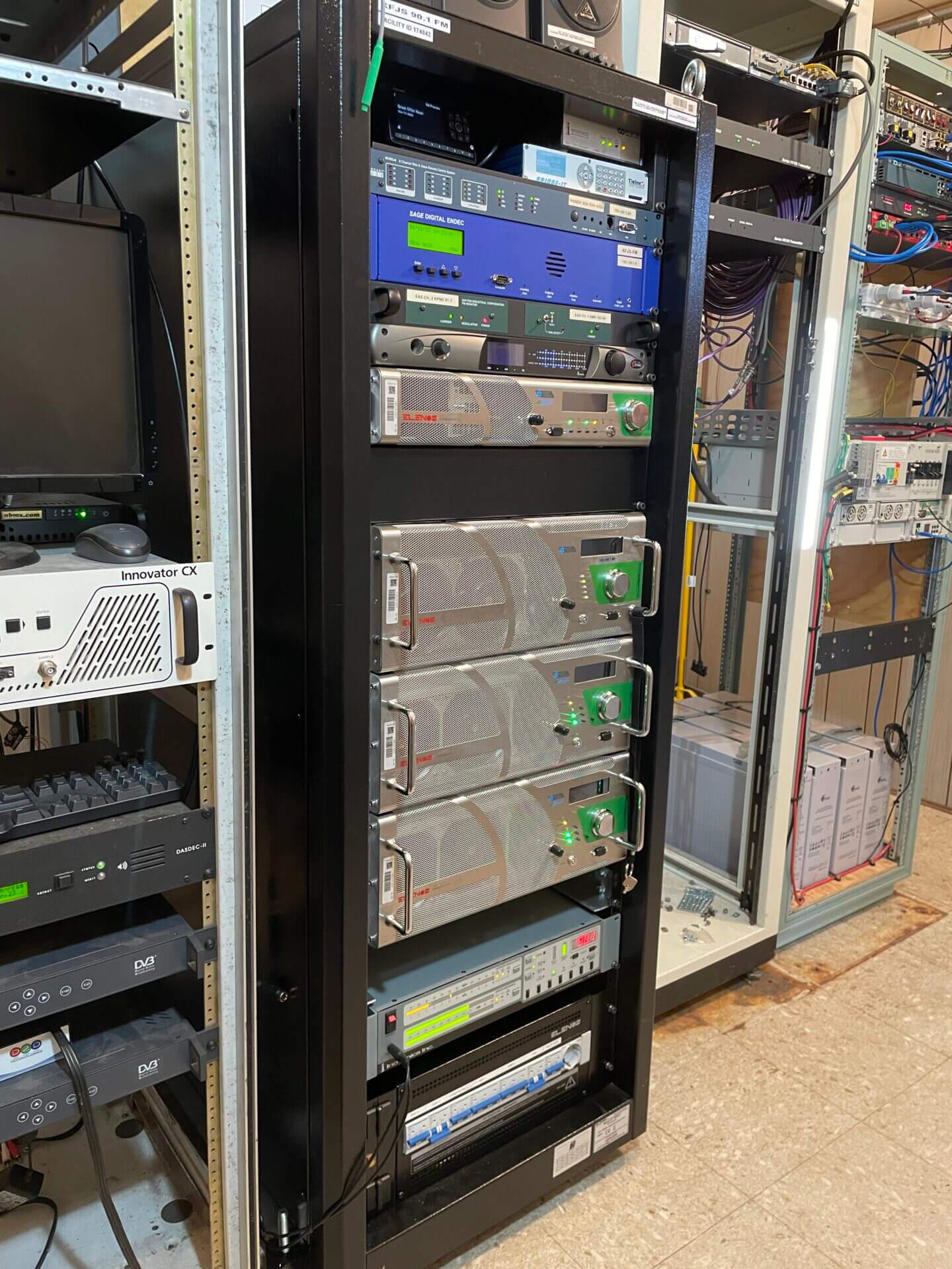
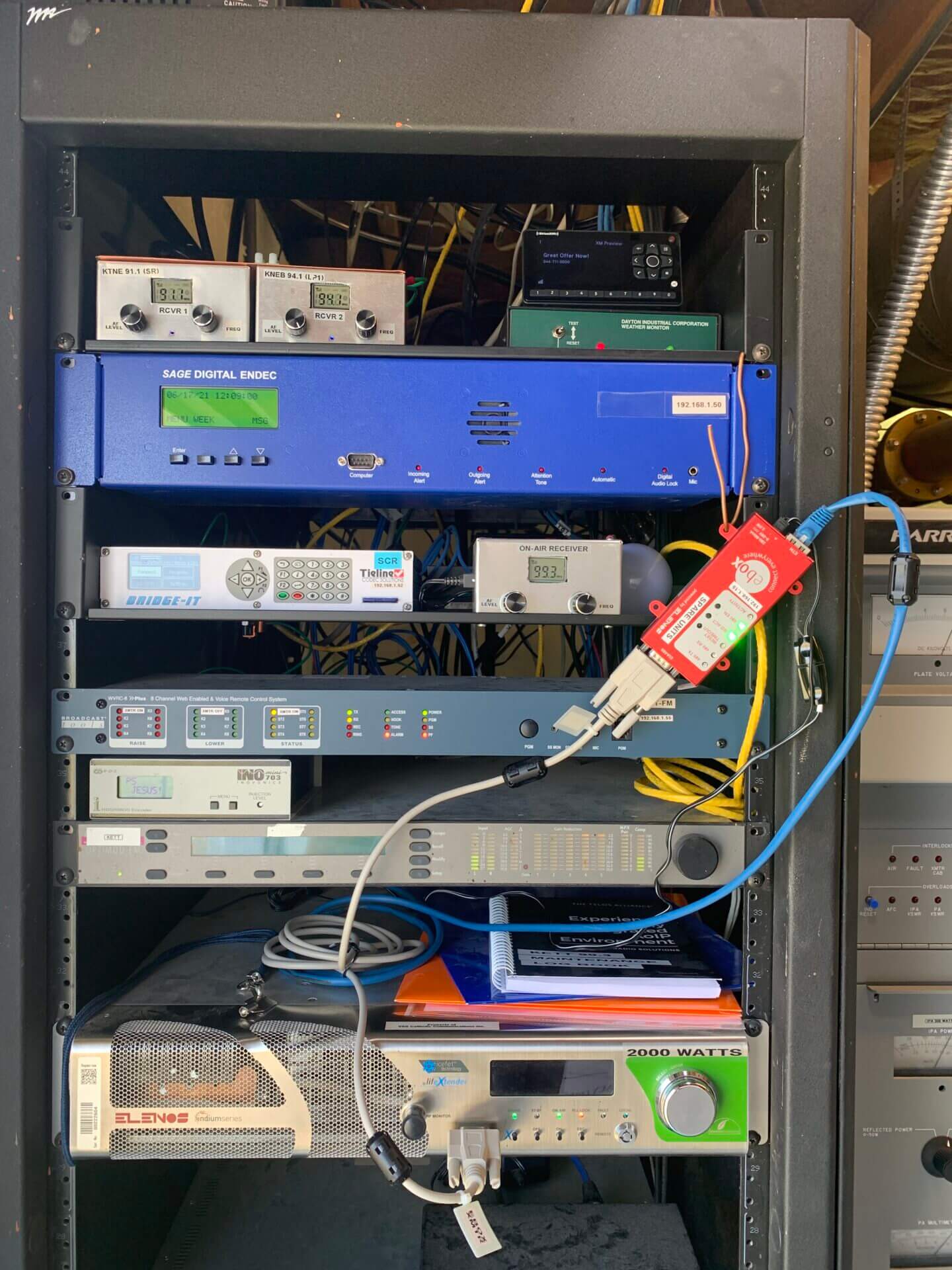
On this page you will see the “technical” side of the network.
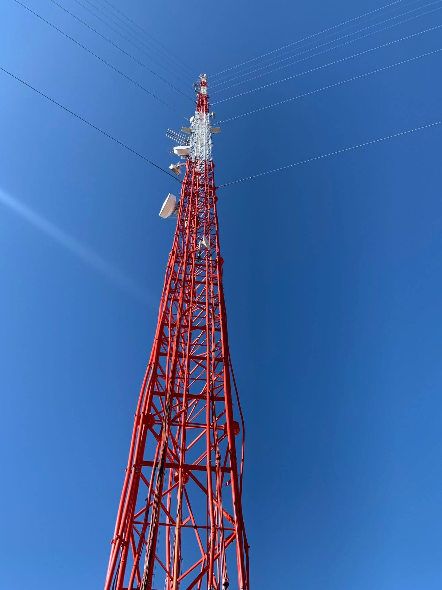
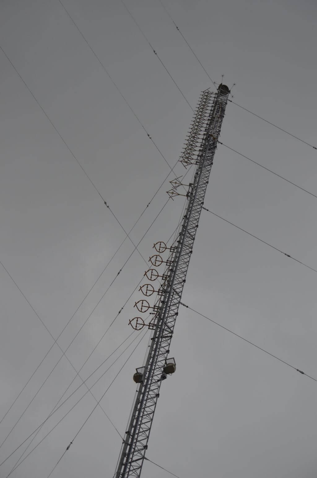
Check out a recent roller coaster of a ride captured on my dashcam during a visit to our KETT Mitchell tower.
We are headquartered with our studios and main offices here in Omaha.


Omaha air studio Production studio
We have 15 transmission sites scattered across Nebraska and one site in west-central Wisconsin. Five of those sites are currently full-power stations (1000 watts and up), two are translators (250 watt repeater stations) and eight Low Power FM – LPFM (100 watt stations) owned and operated by local groups.
Three new signals are scheduled to be built this year. Locations are Ogallala – KETW, Valentine – KVEJ,
and O’Neill – KONL. So stay tuned!!
UPDATE!!
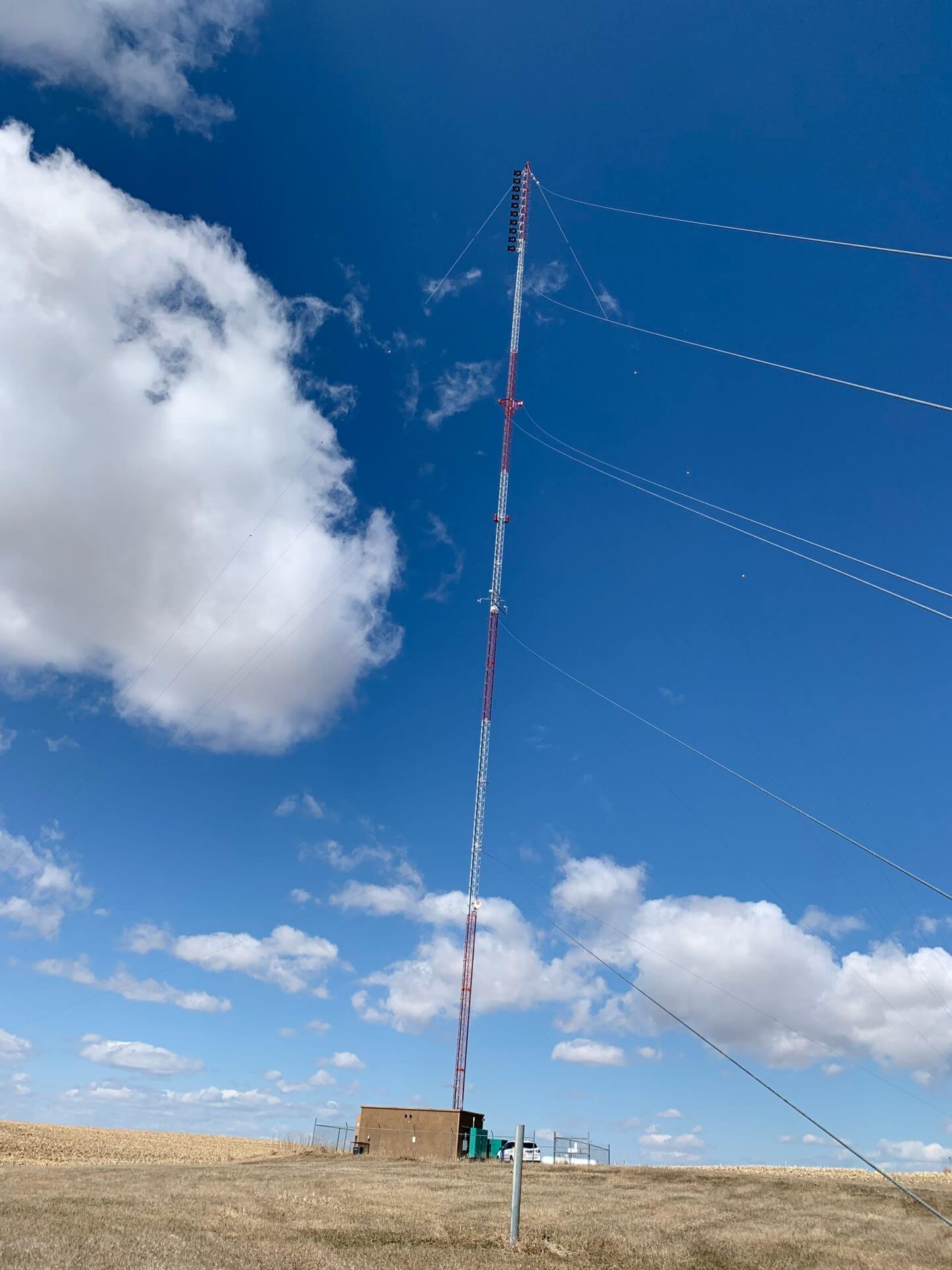
Spirit Catholic Radio is partnering with My Bridge Radio to redevelop a tower site at Valentine for SCR’s KVEJ 91.9 and MBR’s KMBV 90.7 signals. We have cleaned up the site by removing six unused satellite dishes, dirt work requiring leveling of the space for a shelter to be placed, and finally a layer of rock spread and packed. A prefab building and electrical will be installed in short time then a tower crew will be on site to install the antennas for both stations. A ground system was installed around the circumference of the building with six ground rods and number four stranded wire in the form of a halo ground. The building ground is bonded to the tower ground and will be bonded with electrical ground.
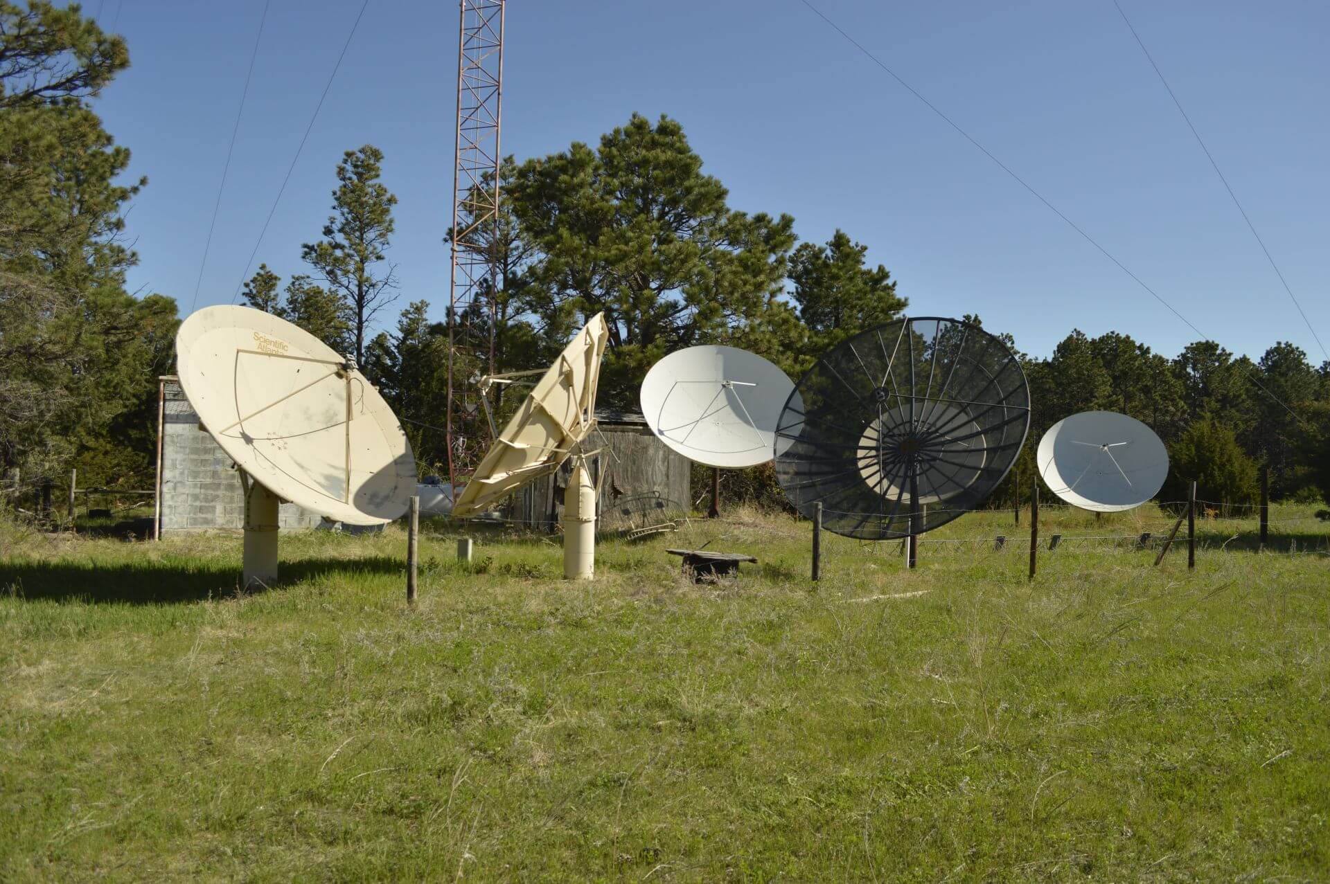
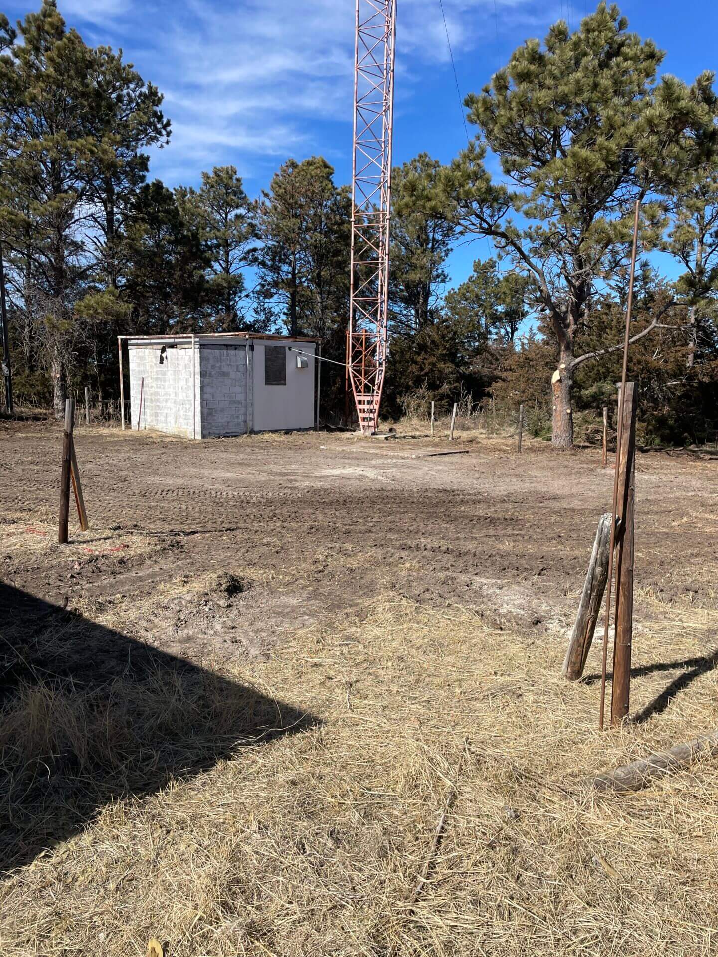
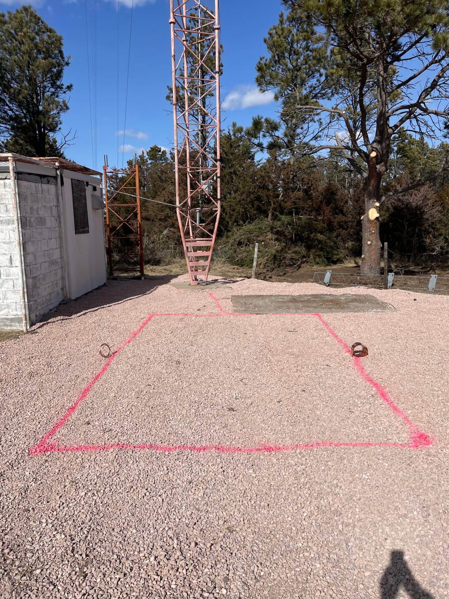
Before…………. And…………. After…………..
Building is complete and antennas/transmission lines are on the tower.
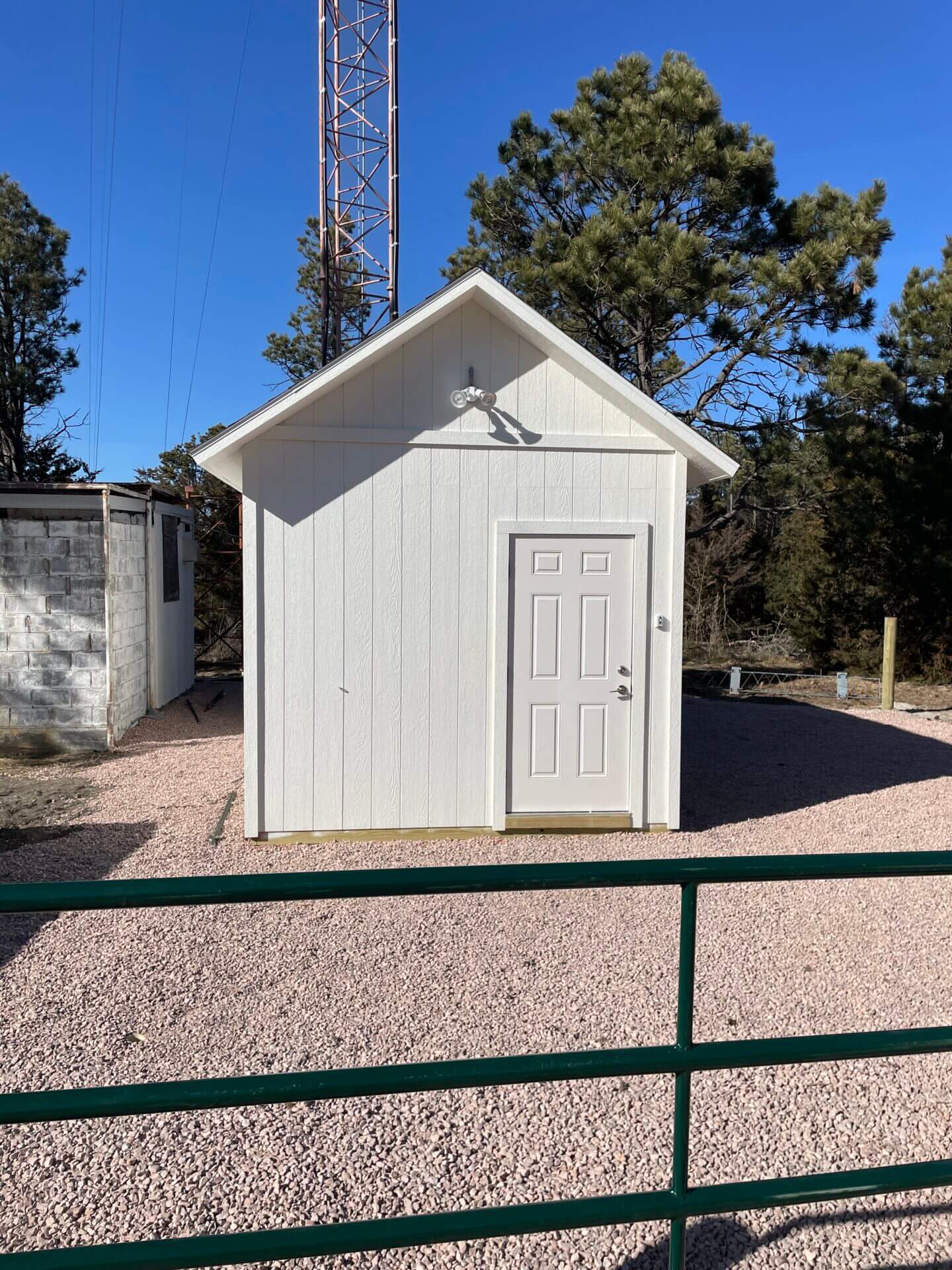
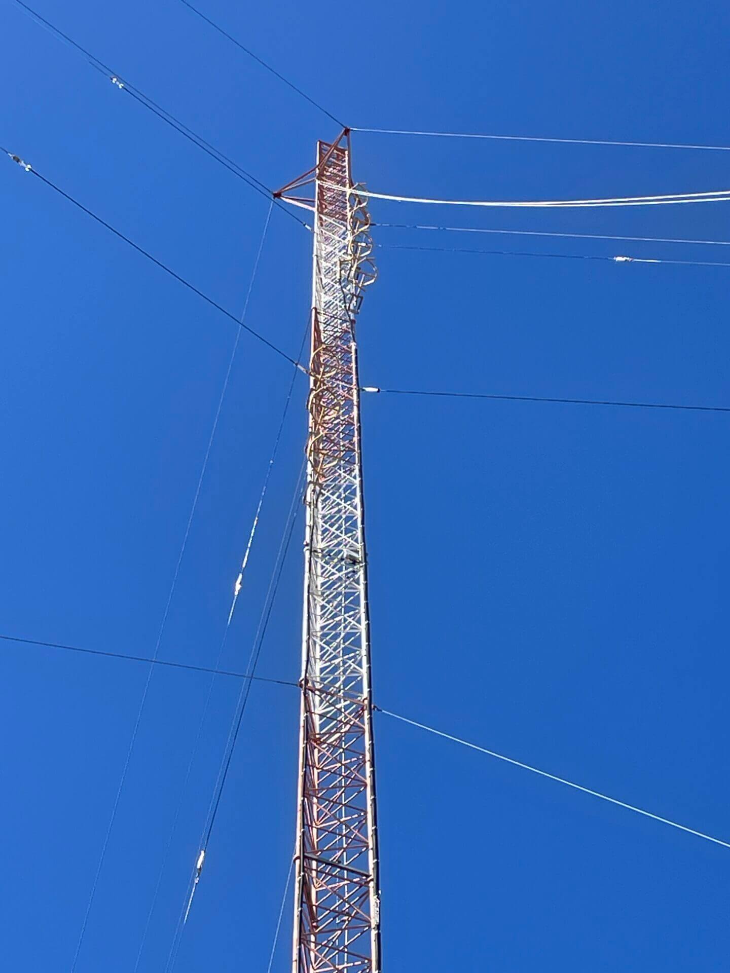
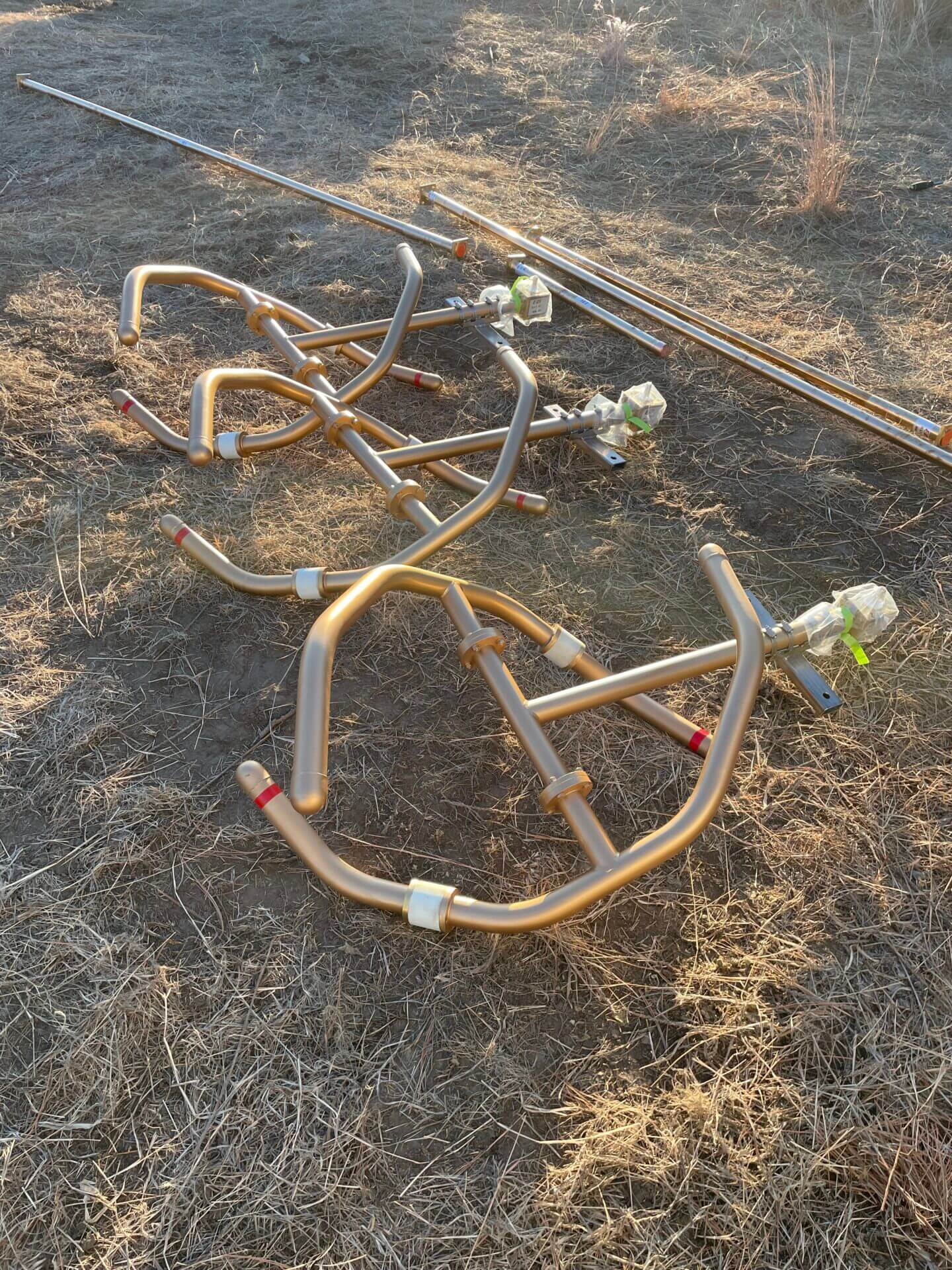
Shelter Tower with both antennas KVEJ antenna
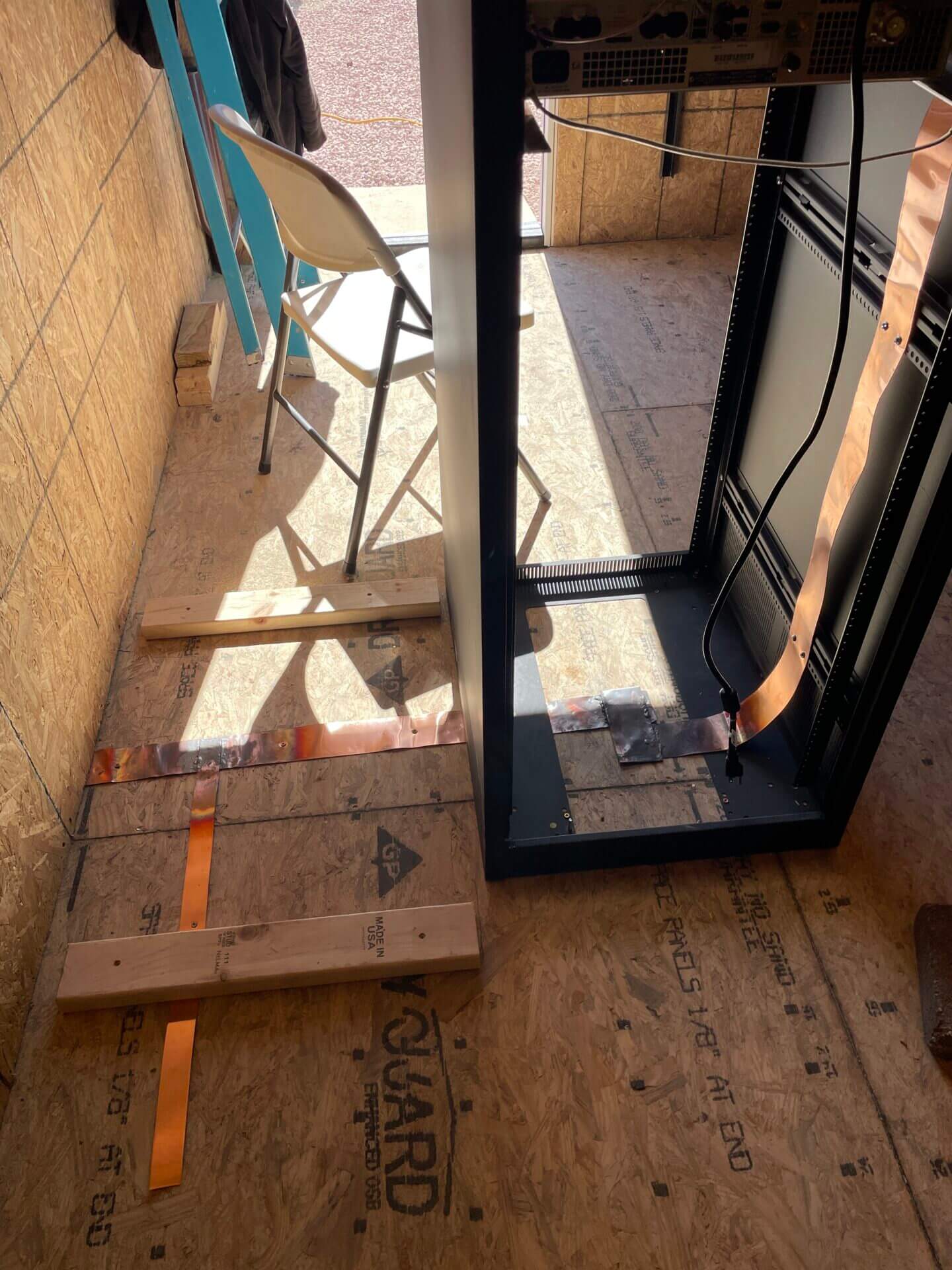
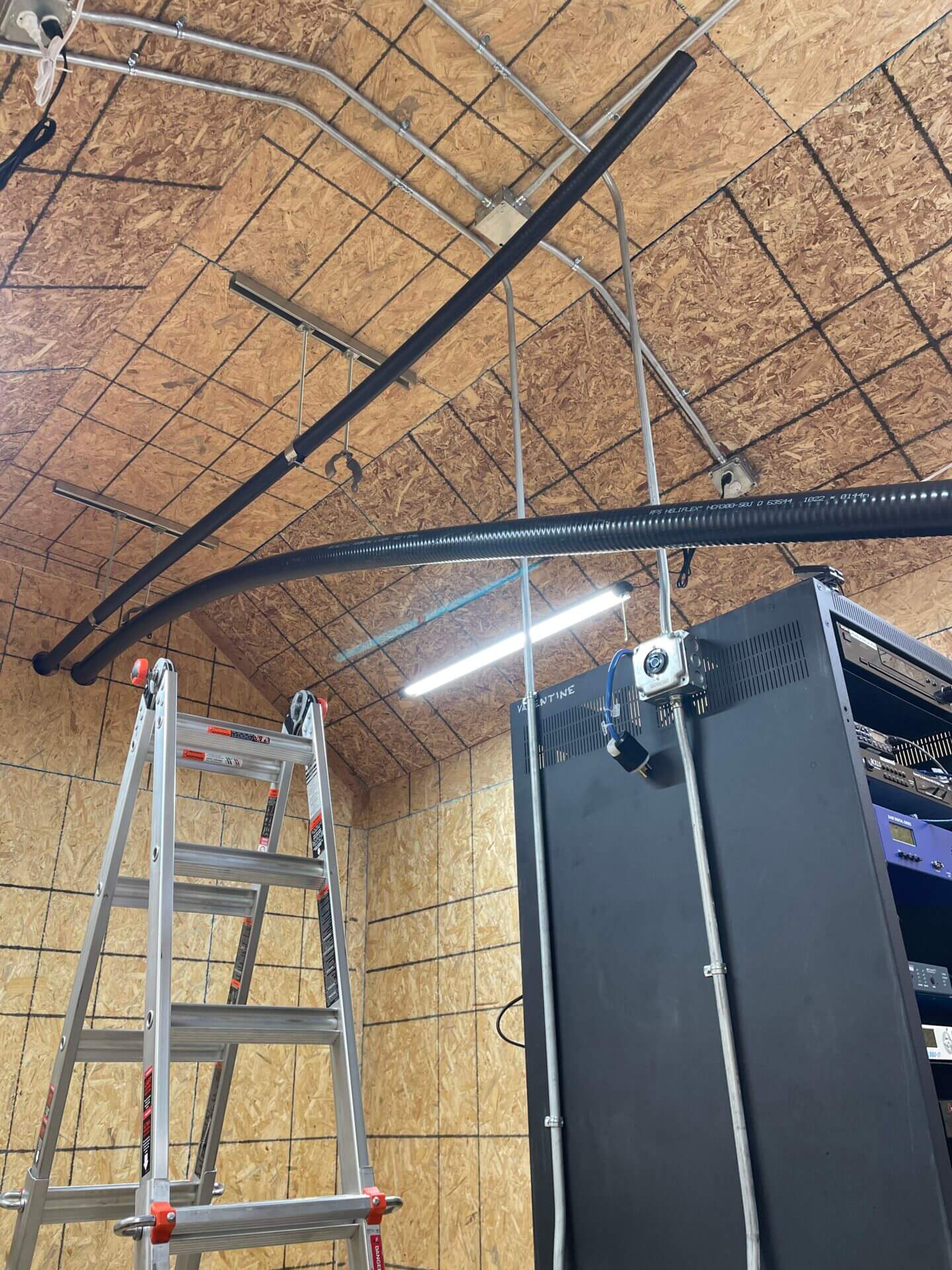
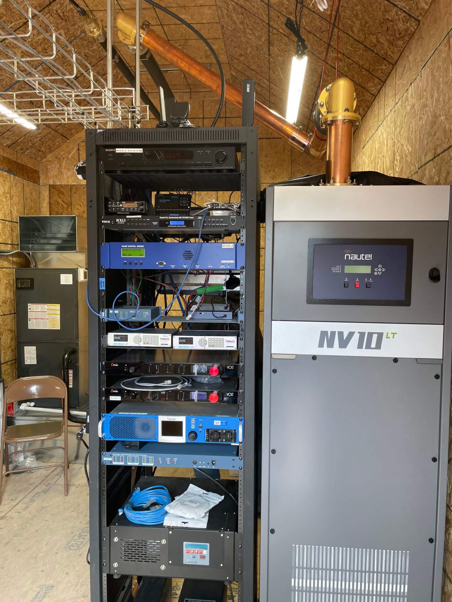
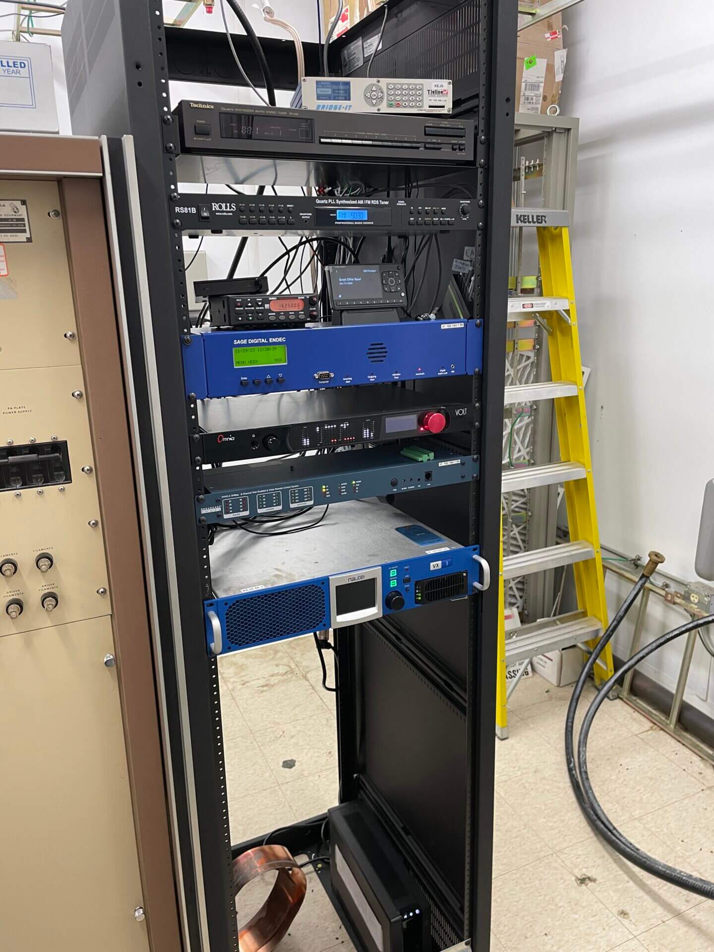
Grounding for rack and transmitter Transmission lines in the shelter Transmitters are in place, waiting for internet service to go on.
KEEP CHECKING BACK FOR MORE ON THIS PROJECT!
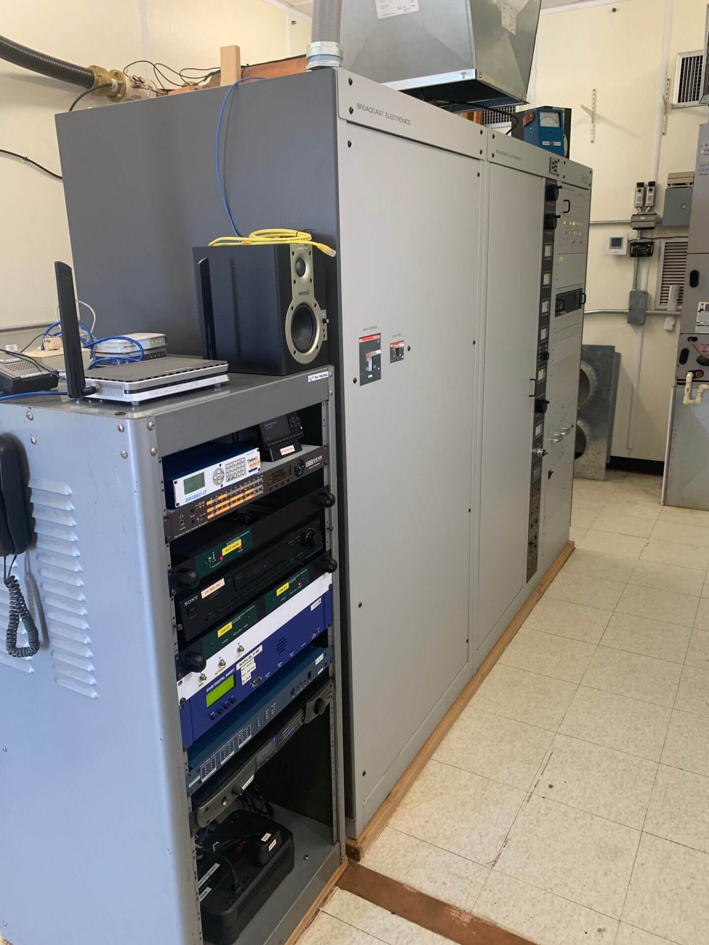
Transmitter upgrades are also happening here at Spirit.
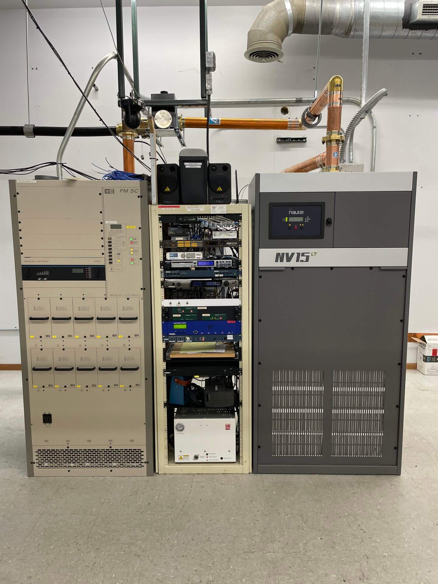
The KVSS transmitter was replaced with a new solid-state transmitter. As our power output remains the same the new transmitter is more efficient. The BE transmitter has had a new tube installed and is ready for backup if needed.
The KFJS transmitter was replaced with a bigger unit. We upgraded power at North Platte from 1.5 kW to 13.2 kW so the transmitter installed is 10 kW. The old 2 kW transmitter will be in place for backup if needed.
The KJWM transmitter was replaced with a bigger unit as well. We upgraded power for Grand Island from 11.5 kW to 35 kW. The new transmitter is 15 kW versus the current the current BE 5 kW transmitter, the BE will become the backup if needed.
UPDATE!!
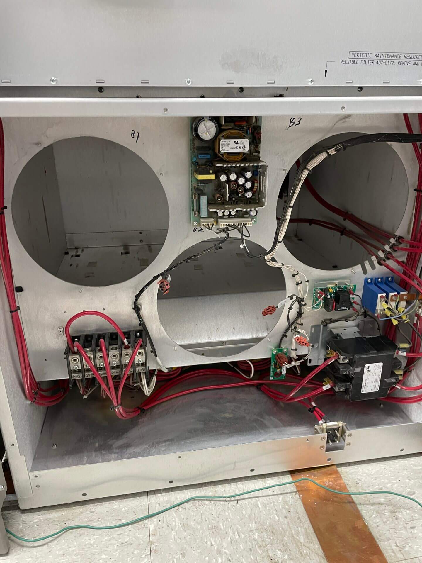
The electrical infrastructure at the KOLB site has been upgraded to incorporate both transmitters.
The KOLB transmitter will be replaced with a new solid-state transmitter. Our power output will remain the same. The current BE transmitter will become the backup once the new one is commissioned on the air.
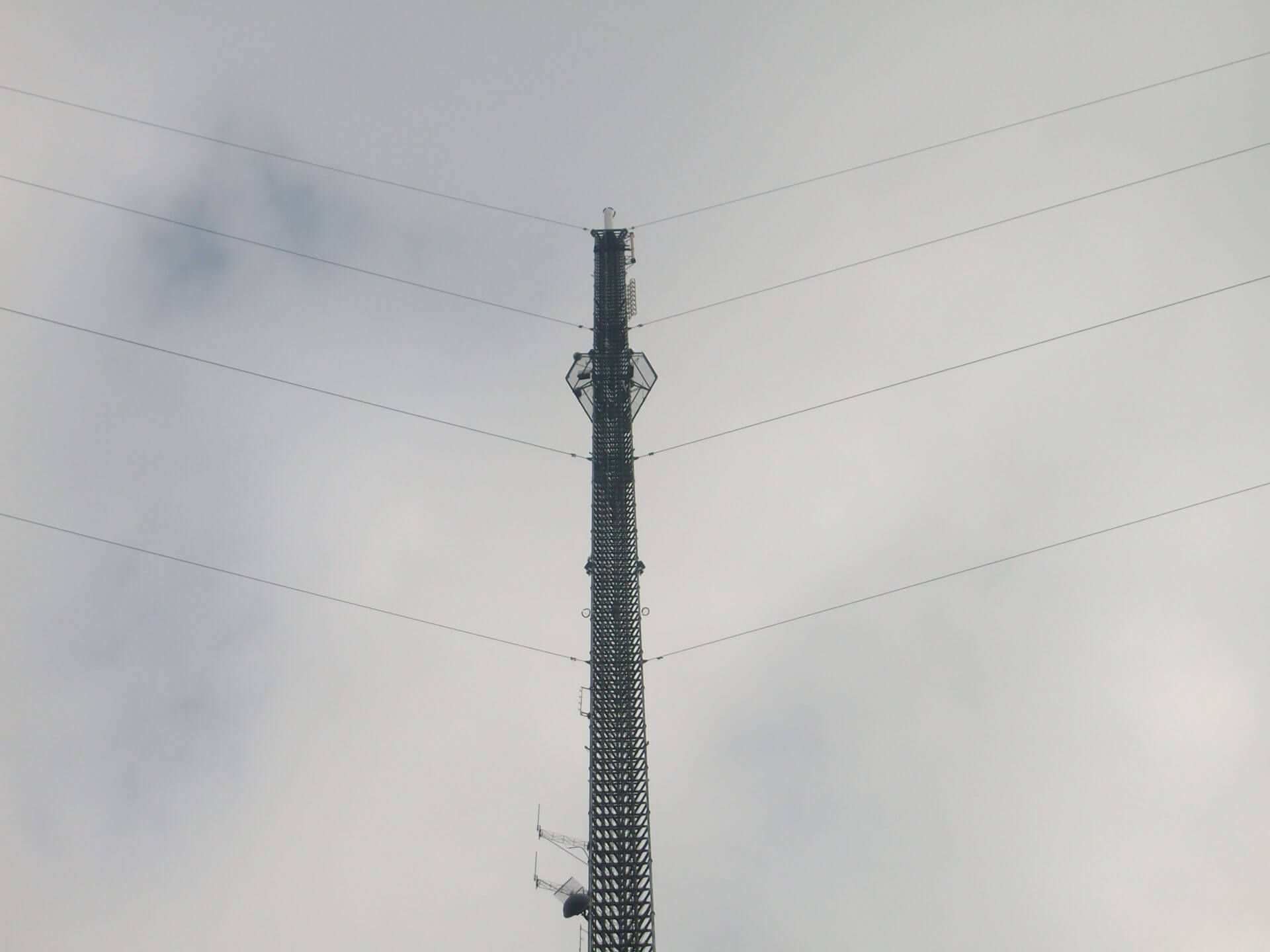
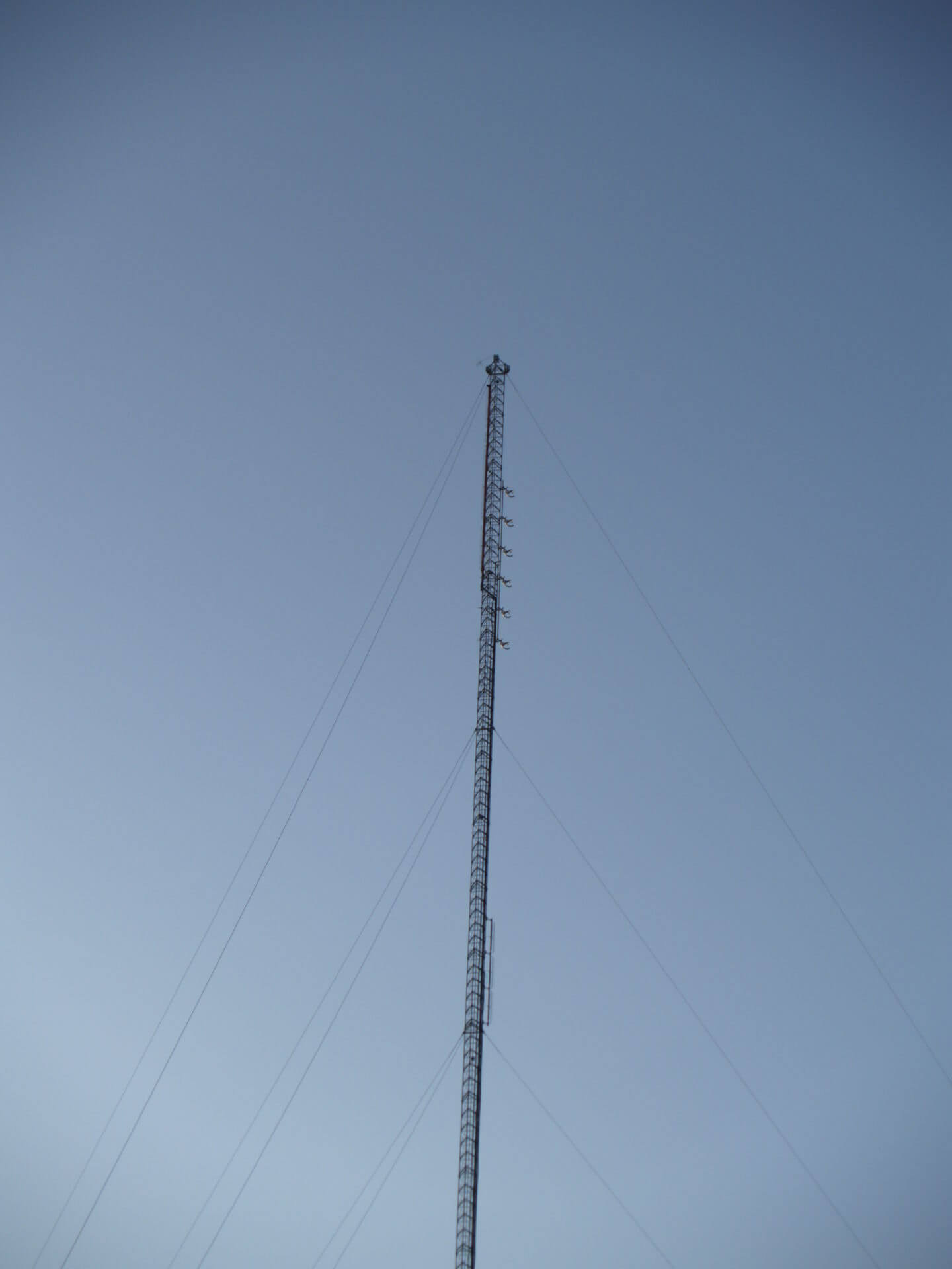
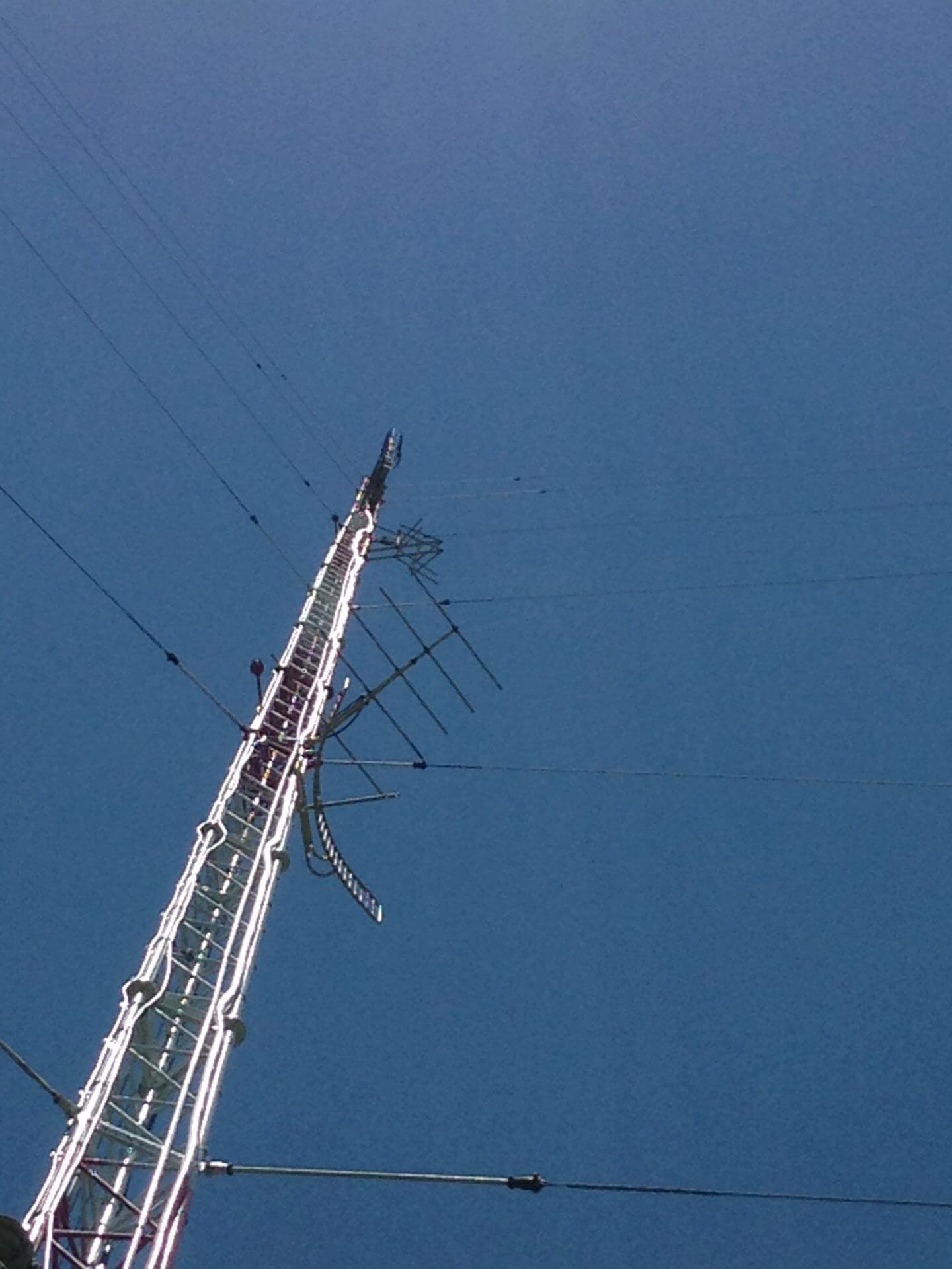
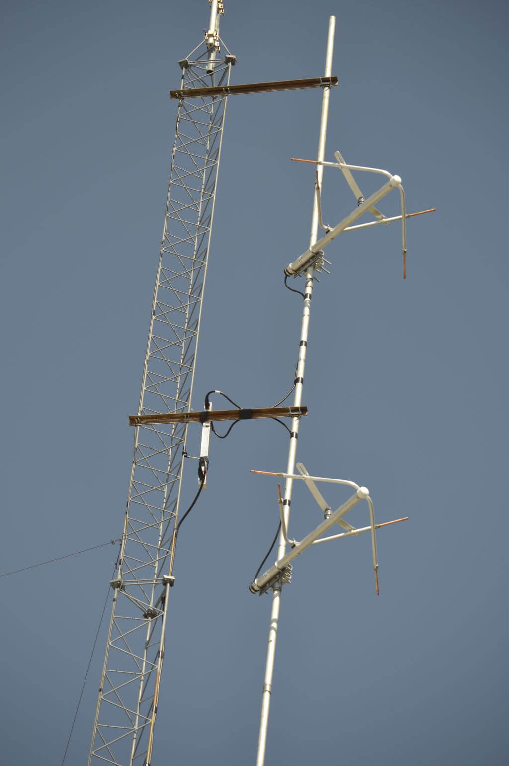
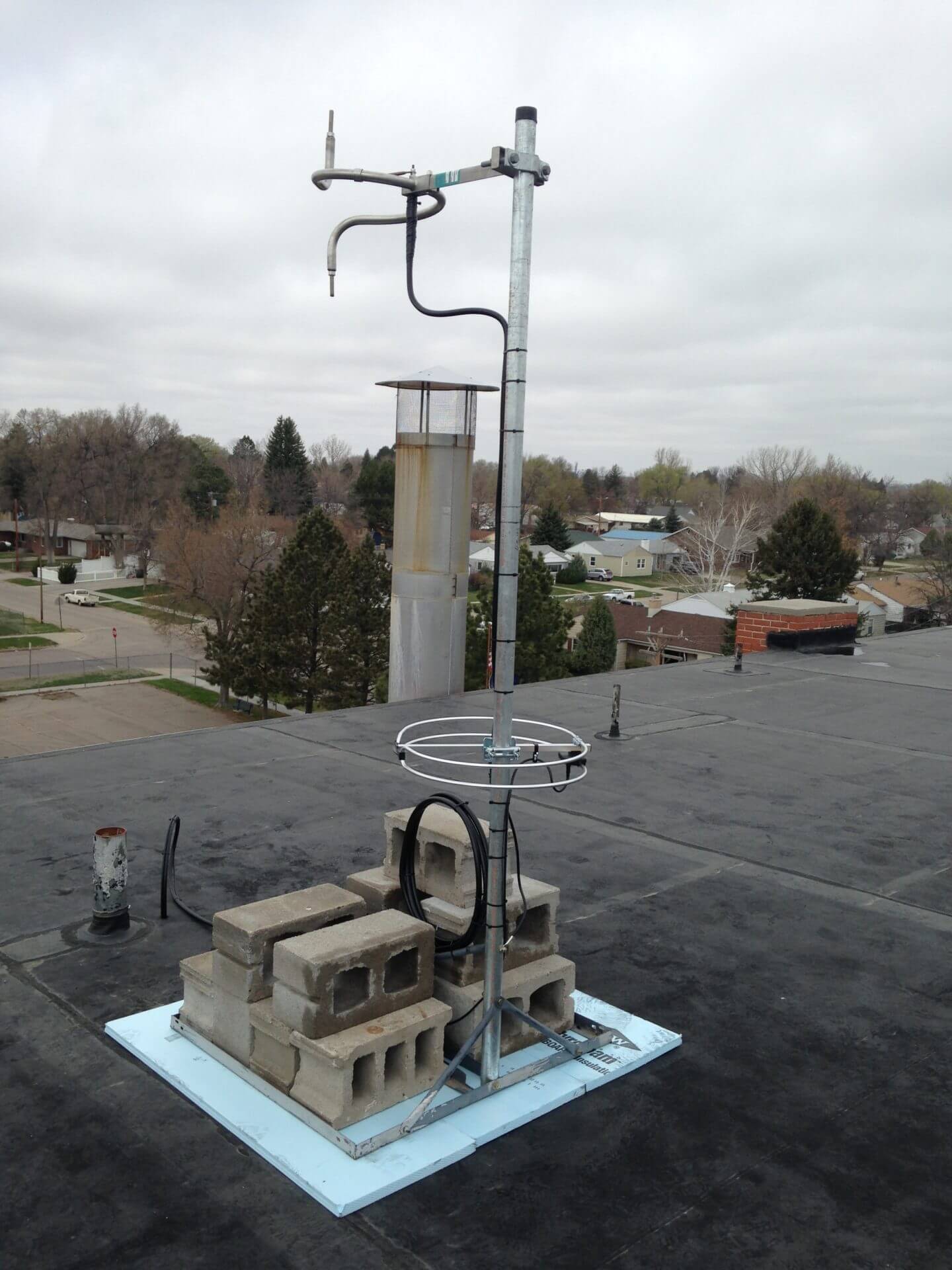
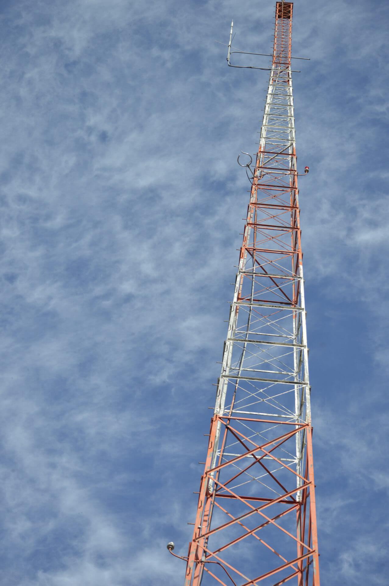
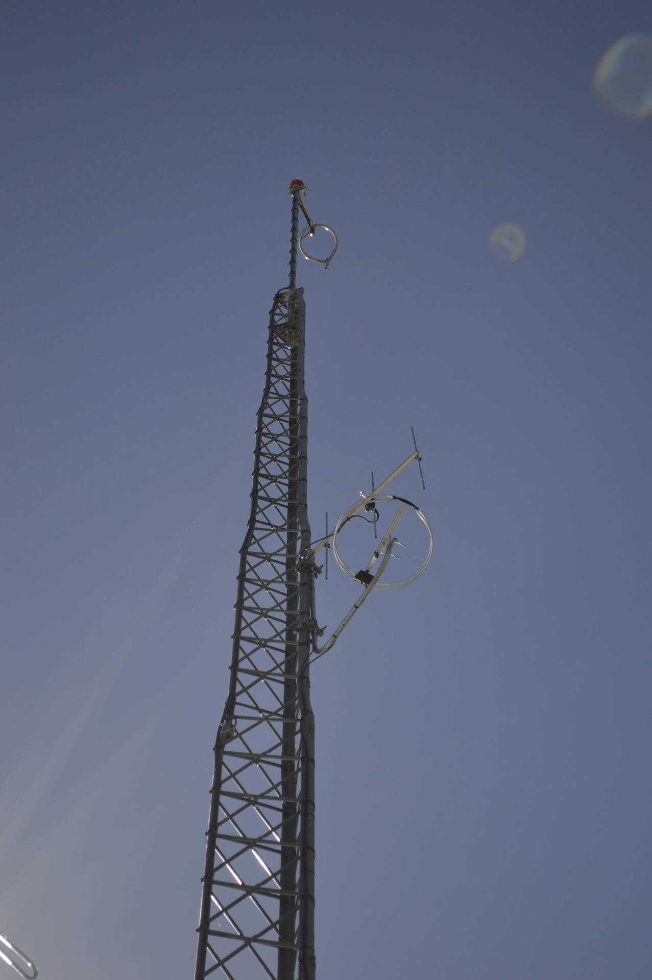
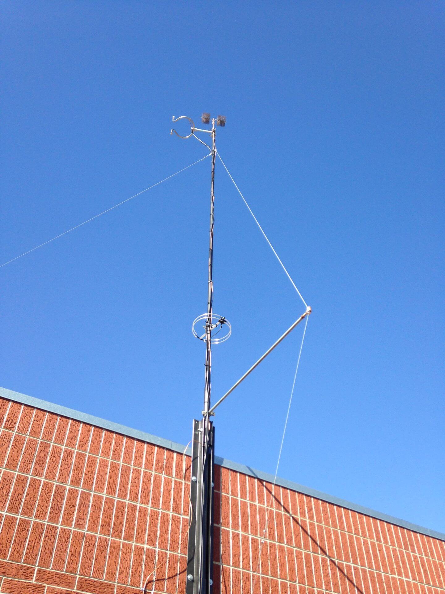
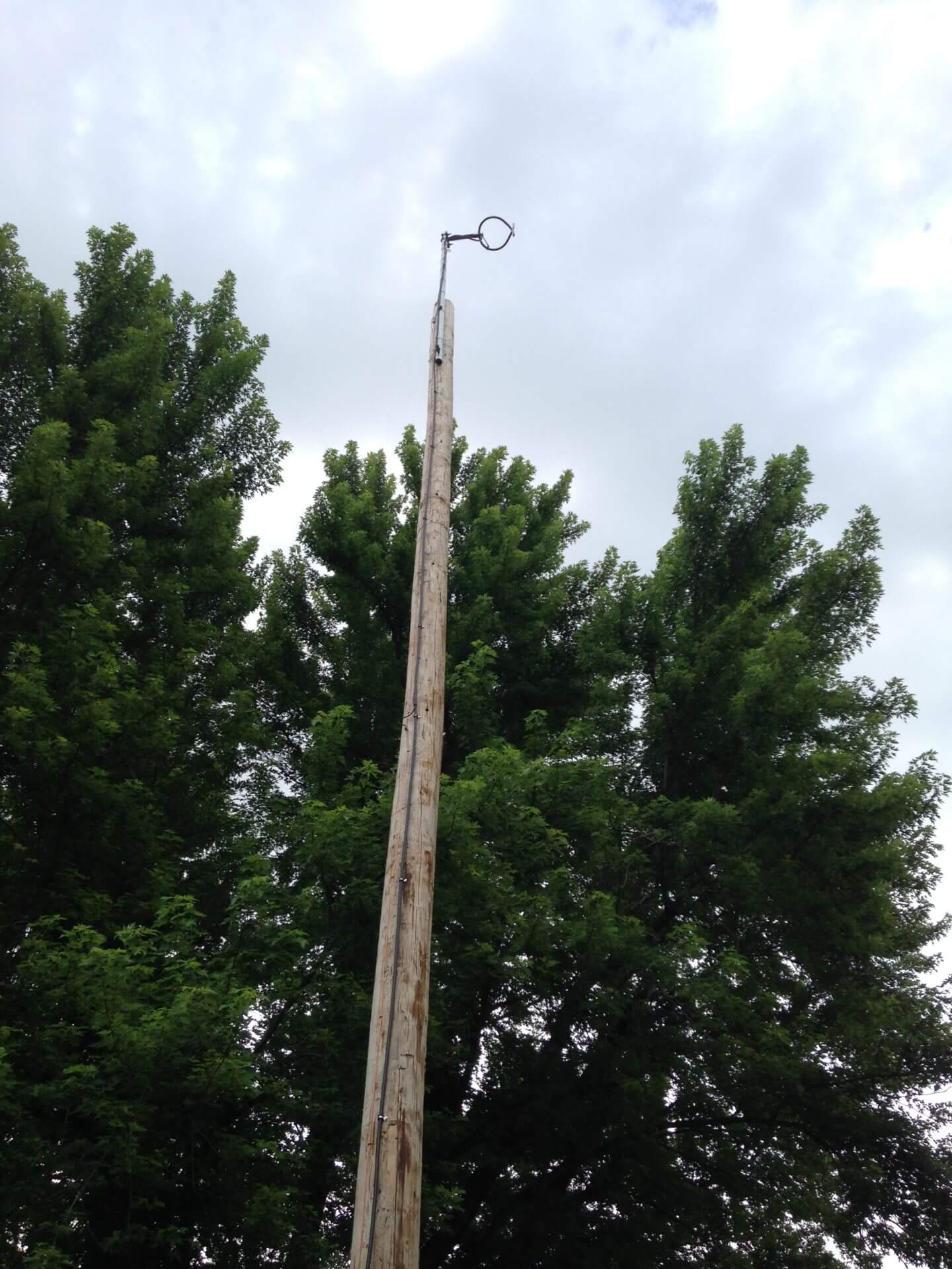
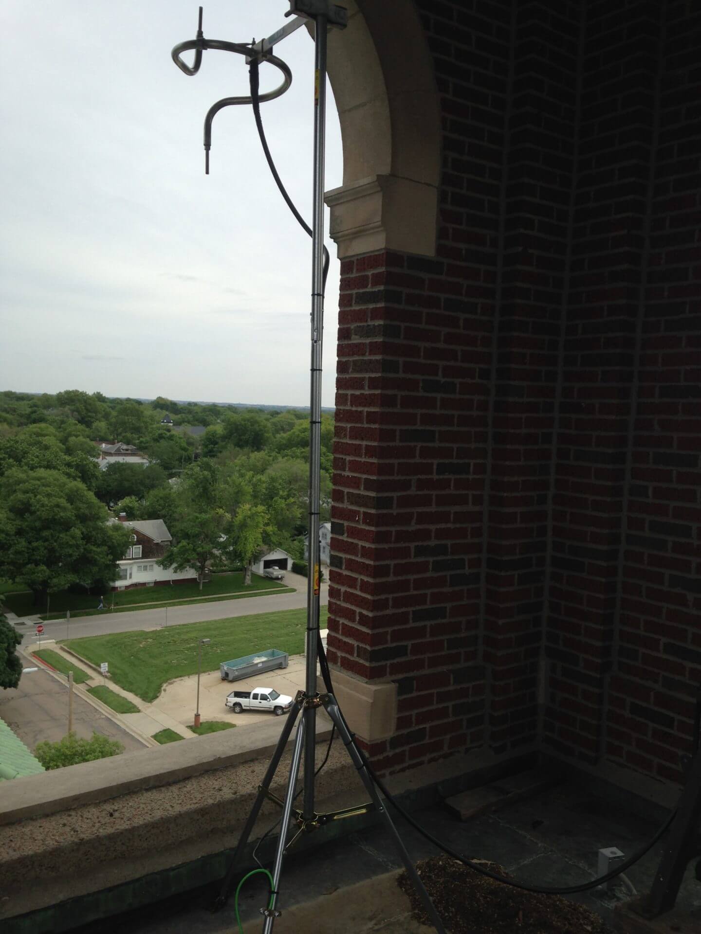
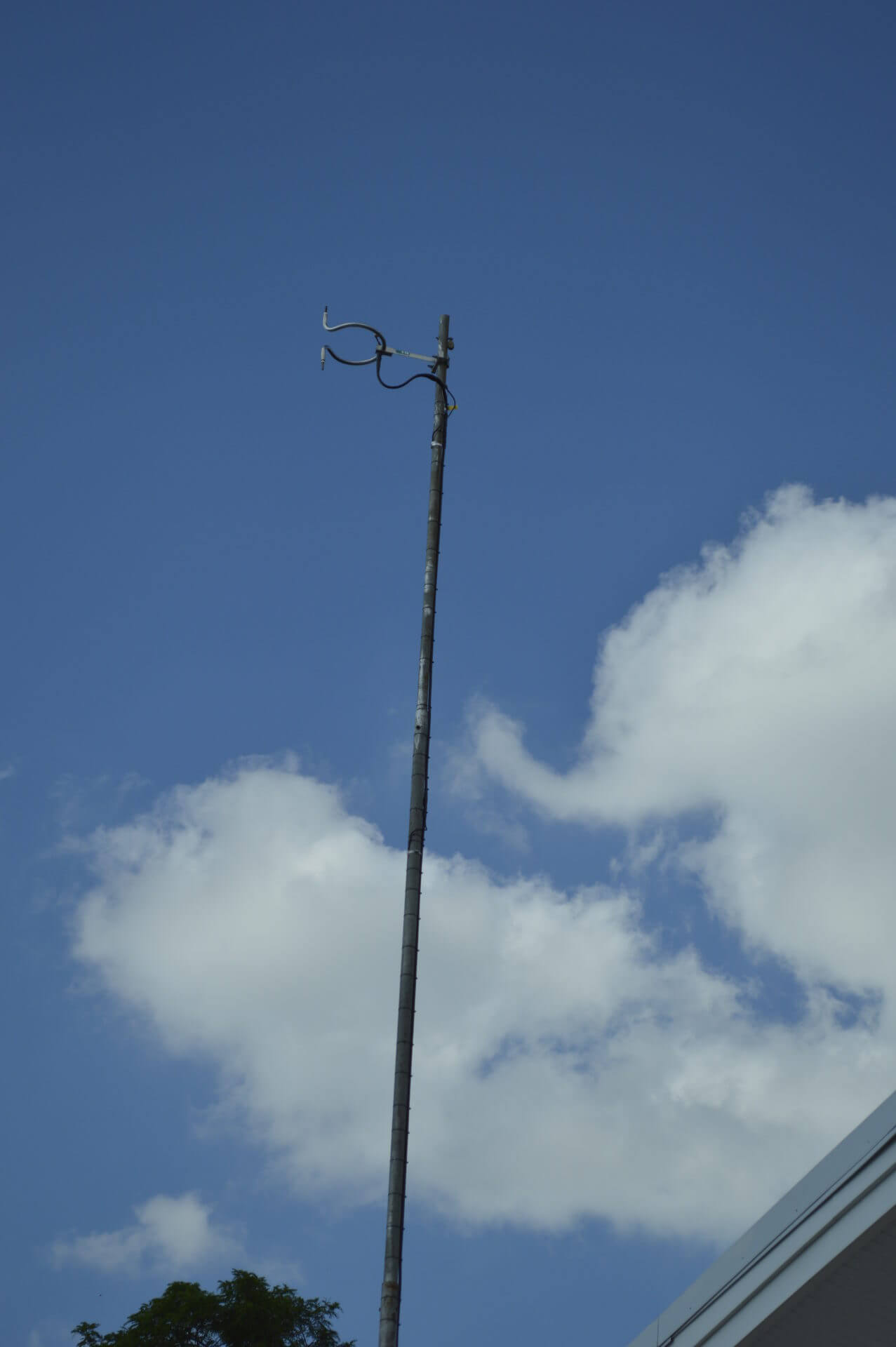
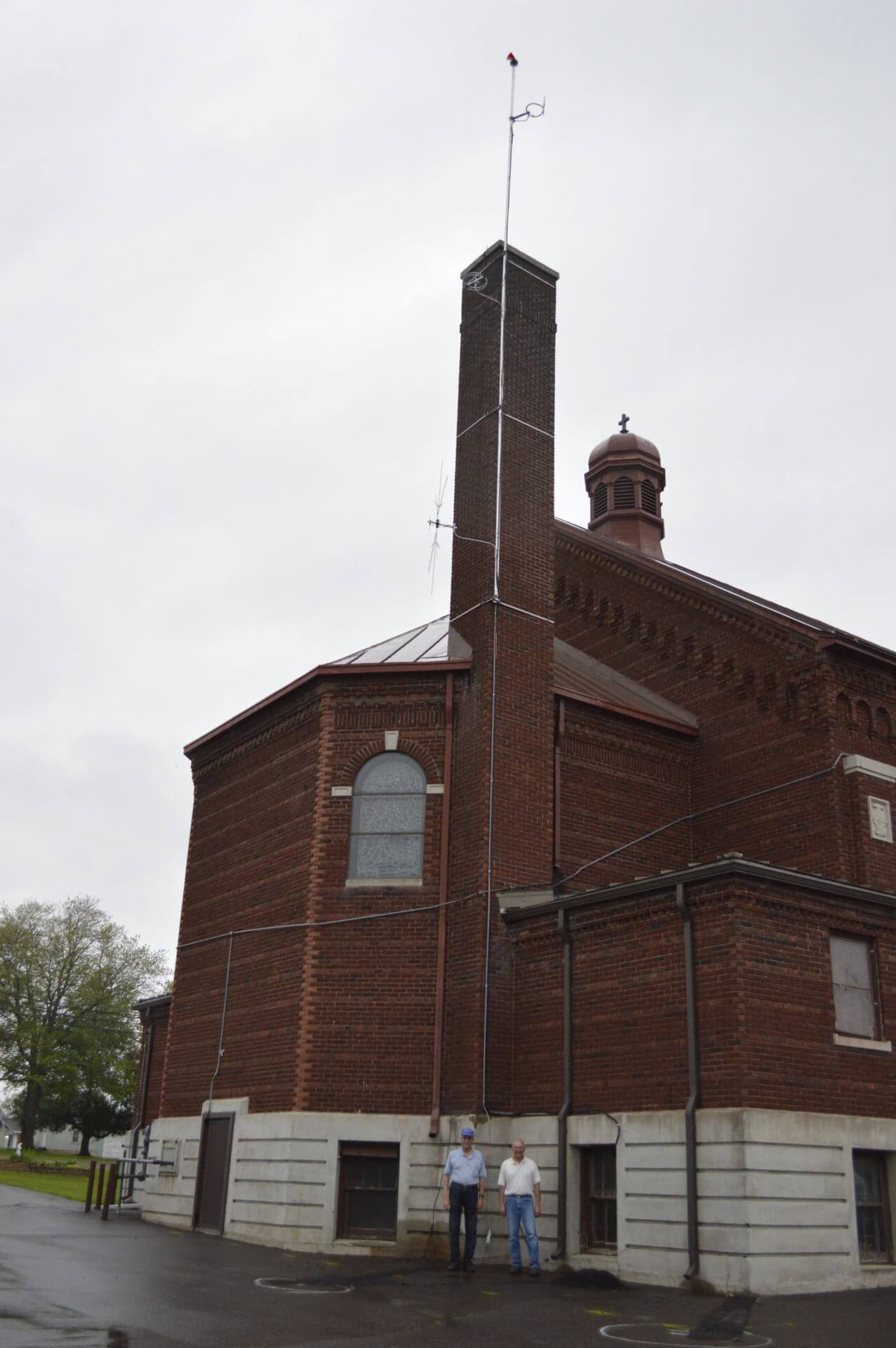
Our work here requires the use of many tools and test equipment in order to maintain our network of stations. Recently I had to deal with an antenna issue with one of our LPFM affiliates. The antenna is 75 feet above the ground and beings I don’t climb towers anymore a crane with basket was brought in to get me to the antenna.


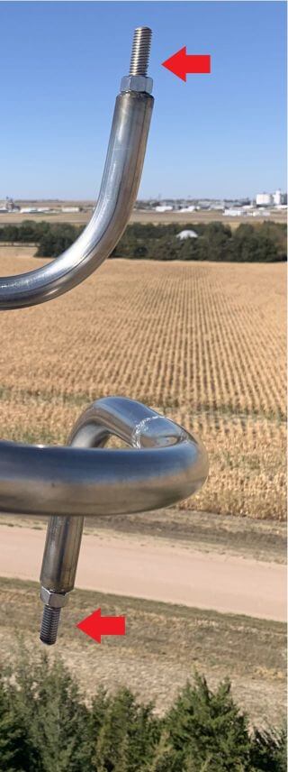
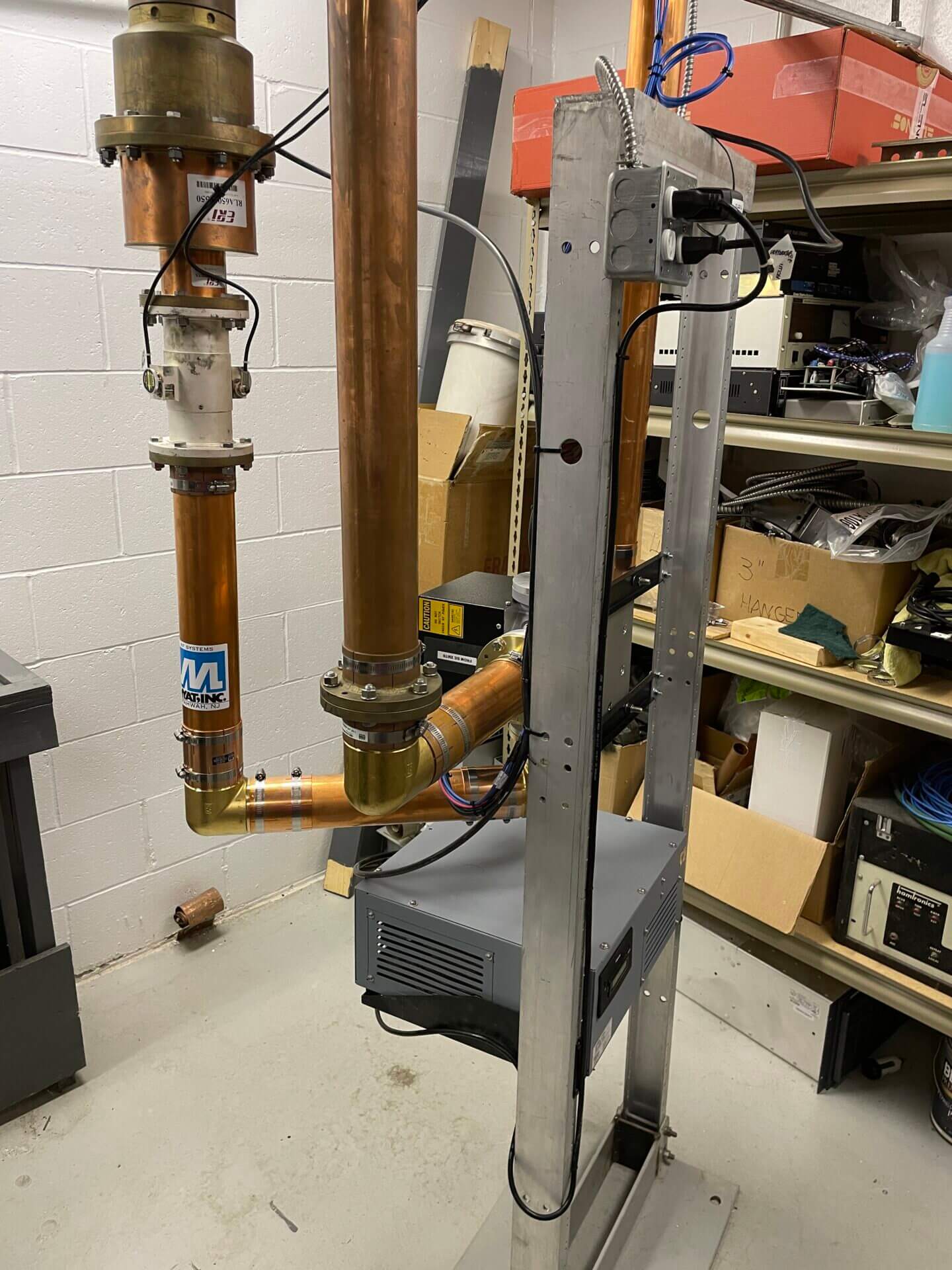
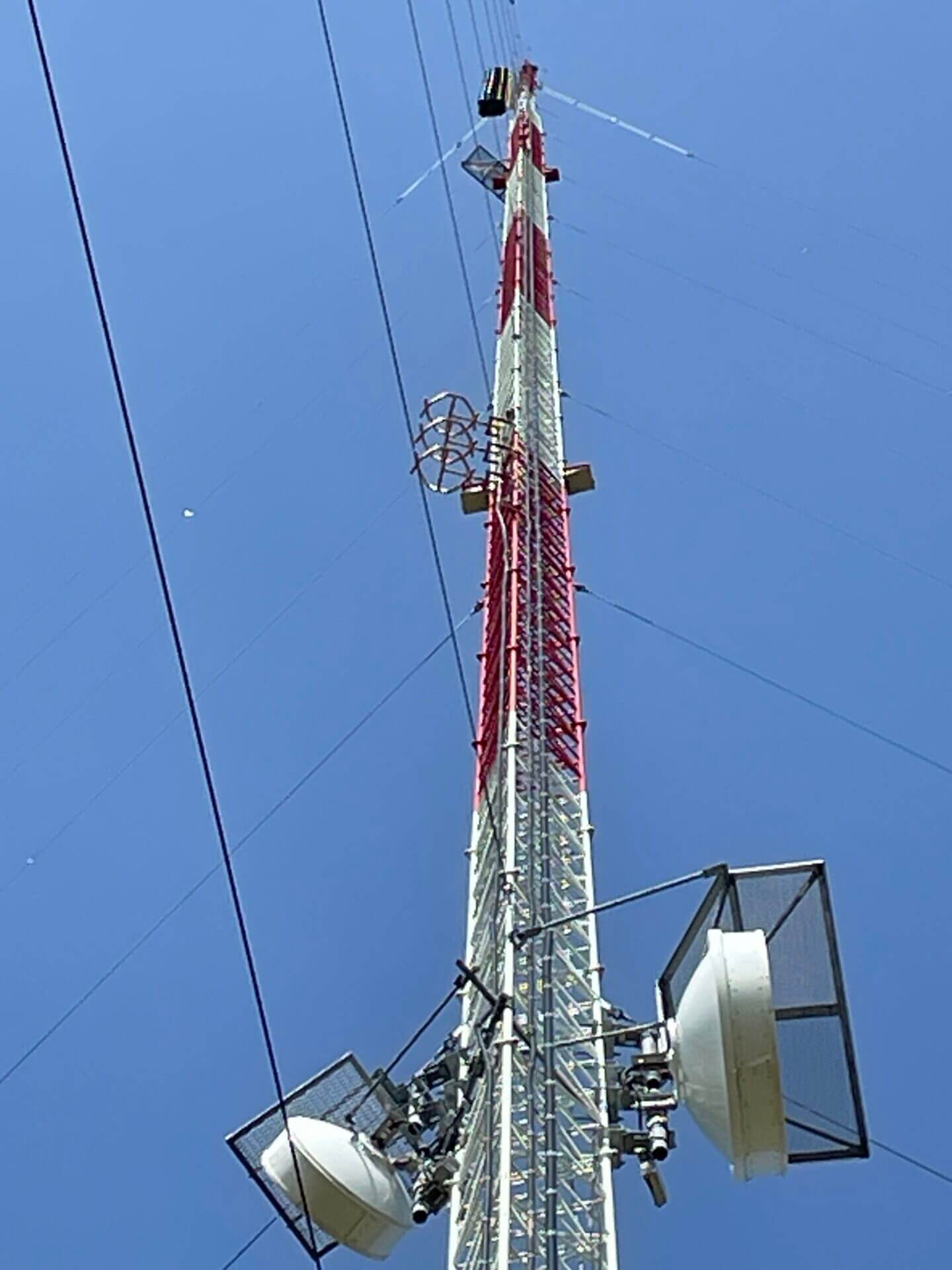
The antenna shown in the second image is what is called a circular polarized antenna, both vertical and horizontal polarization. Most vehicles have vertical receive antennas and radios in the home usually have horizontal receive antennas. The problem was that the antenna was no longer tuned on frequency for the station at 104.3 MHz(Megahertz) therefore causing a problem with a large amount of reflected power shutting down the transmitter. When an antenna is tuned to the station’s resonant frequency power output of the transmitter(forward power) is at 100% with no power being reflected back to the transmitter however if the antenna is mis-tuned or loaded down with snow or ice some of the power will be reflected back into the transmitter. Most transmitters will handle reflected power to a limit and then will protect themselves by lowering power or shutting down. Referring to the third image of the antenna you will notice the elements(red arrows) can be adjusted to tune.
To tune the antenna I use assorted pieces of test equipment to measure the adjustments made. The main instrument I use is a Vector Network Analyzer(image below) used to measure the characteristics of the antenna and coax that connects the antenna to the transmitter. The yellow line on the display is the is the main indicator I’m looking at. The dip at the bottom is the frequency 104.3 MHz that the antenna should be at. When the antenna was first measured it was showing a resonant frequency of 104.6 MHz causing the high reflected power and shutting down the transmitter. Until I was able to re-tune the antenna, power on the transmitter was lowered to maintain a listenable signal. This is not the normal activity that I deal with daily but sometimes these special issues do come up.

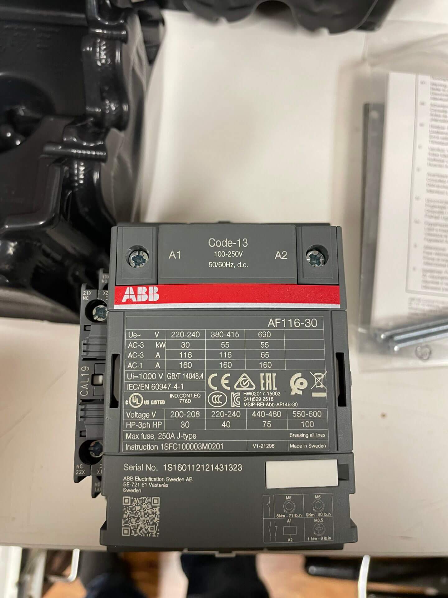
There are times when parts wear out and replacement is necessary. Recently our transmitter up in Northeast Nebraska had problems staying at full power. After intense diagnoses I found one of the power supplies wasn’t getting the required 220 volts. The cause was a high voltage contactor that had failed. After 11 years of running 24/7/365 with heat it just fell apart….
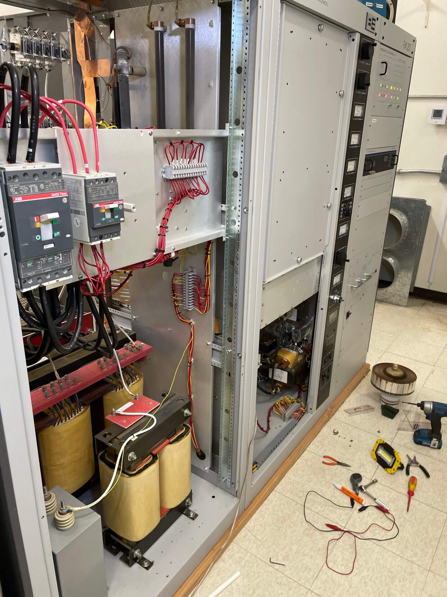
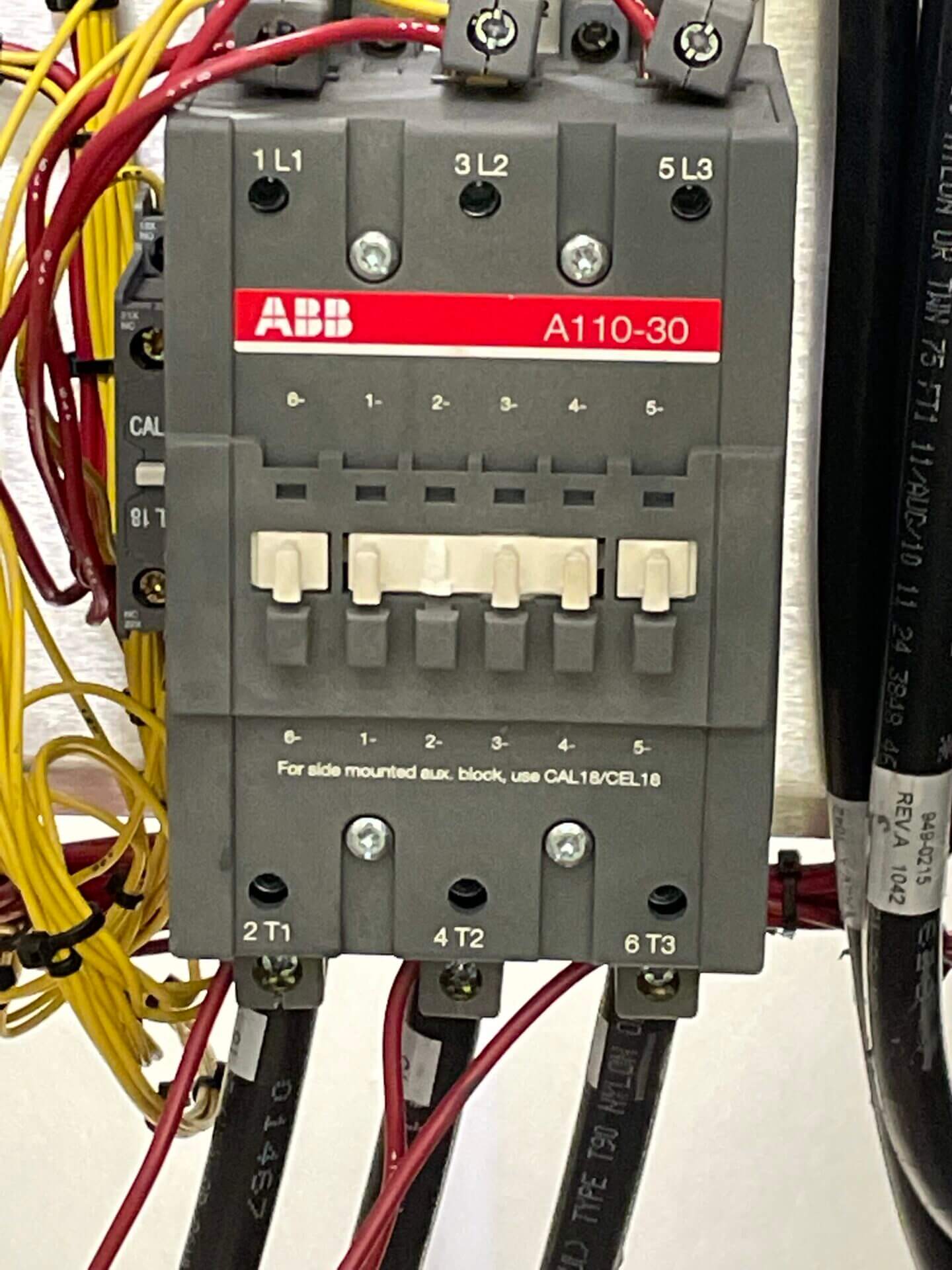
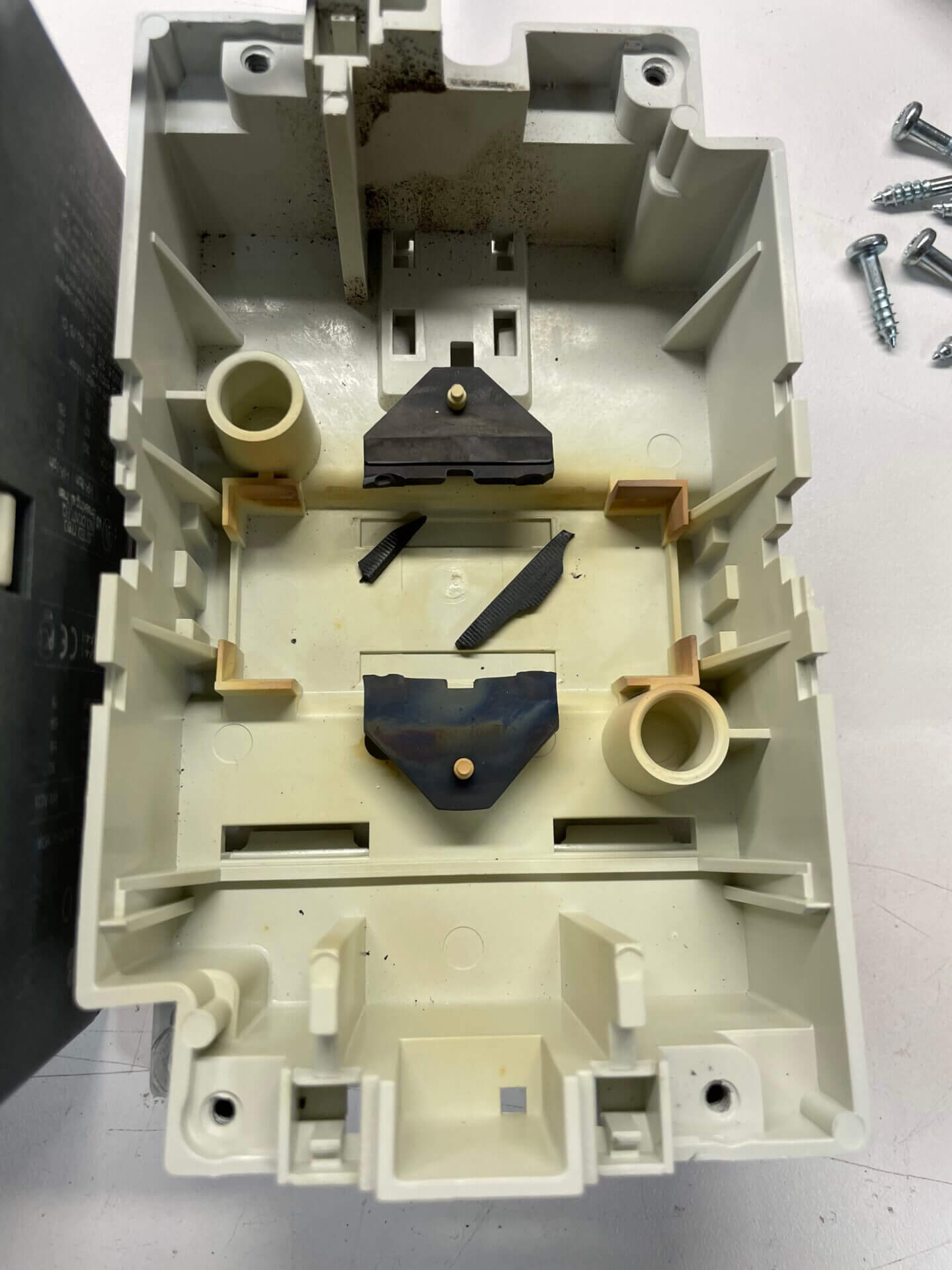
A new contactor installed and we are back to full power!
The repairs continue here at Spirit. Recently our BE FM5C transmitter out at Wood River had a serious heat issue. The transmitter consists of 3 fans
that keep air flowing over the amplifier modules and power supplies as well as the exciter that 1 fan. Two of the three fans locked up and were not working.
The exciter’s fan also locked up and quit working. No spare fans at the site or with us we made a run to Grand Island to find something to get us back up
and running. We ended up getting a floor drum fan to push air through the back where the three fans are and with luck our engineering friends with
NTV in Kearney happened to have fan that would work in the exciter. We ordered new fans for the transmitter and had another spare fan back at the shop
in Omaha. The transmitter was fully repaired and back on the air within 3 hours.
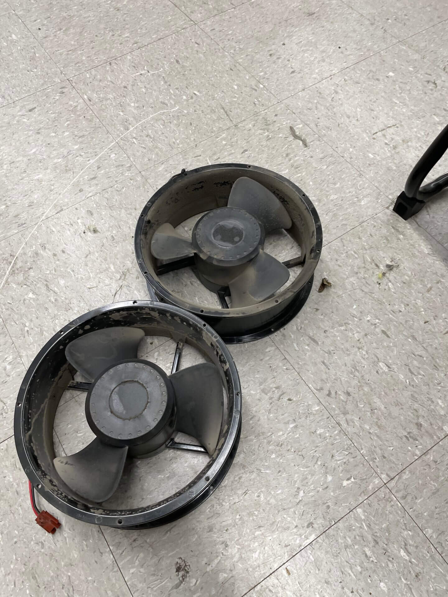
Old fans locked up Old fans removed from transmitter
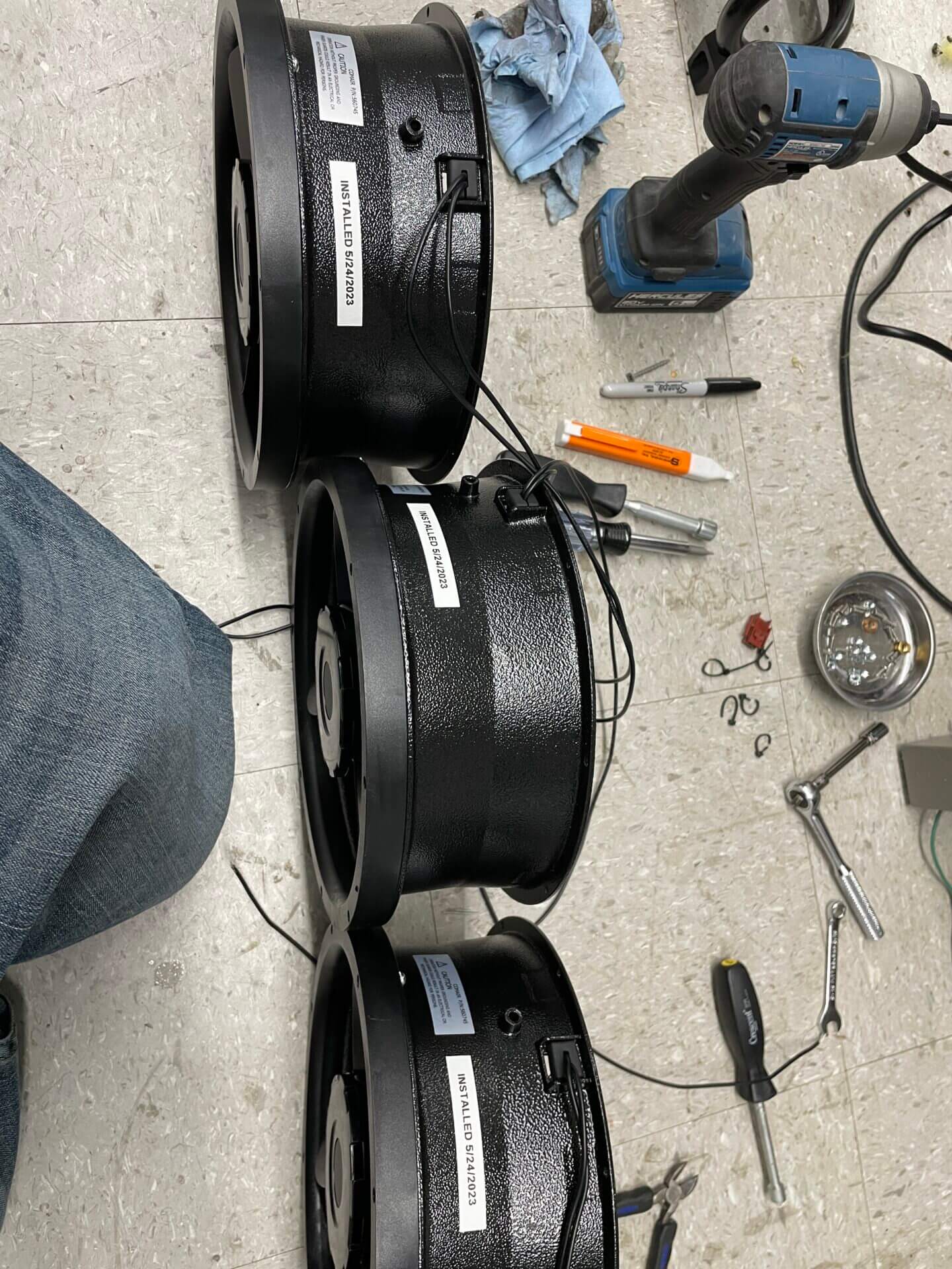
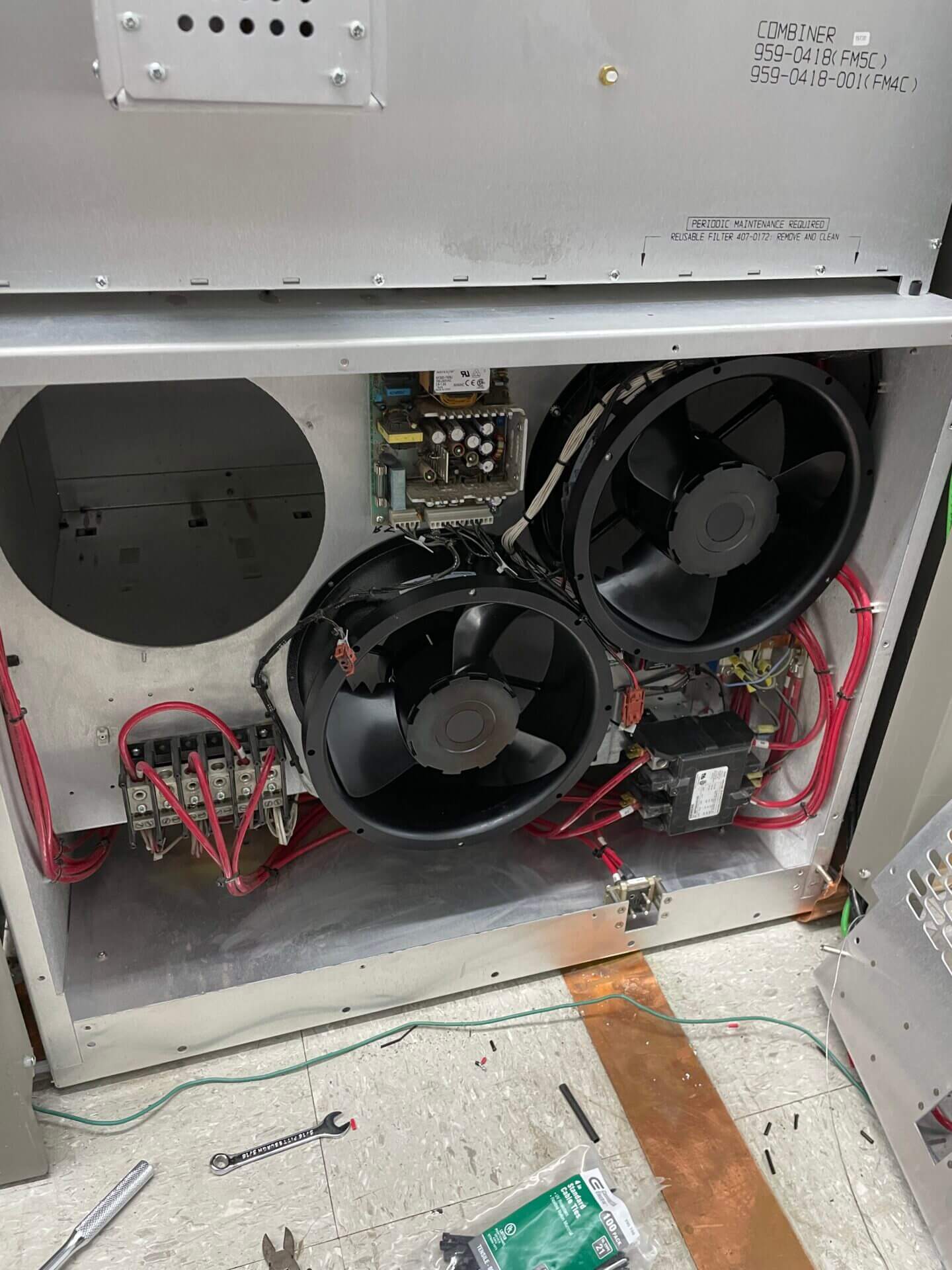
New fans ready to go in Two new fans in, one to go
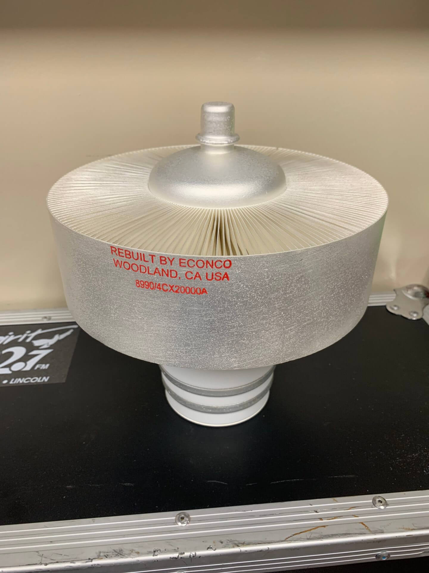
This is the amplifier tube for the KVSS and KOLB transmitters. It has the ability to put out 20,000 Watts
of RF power.
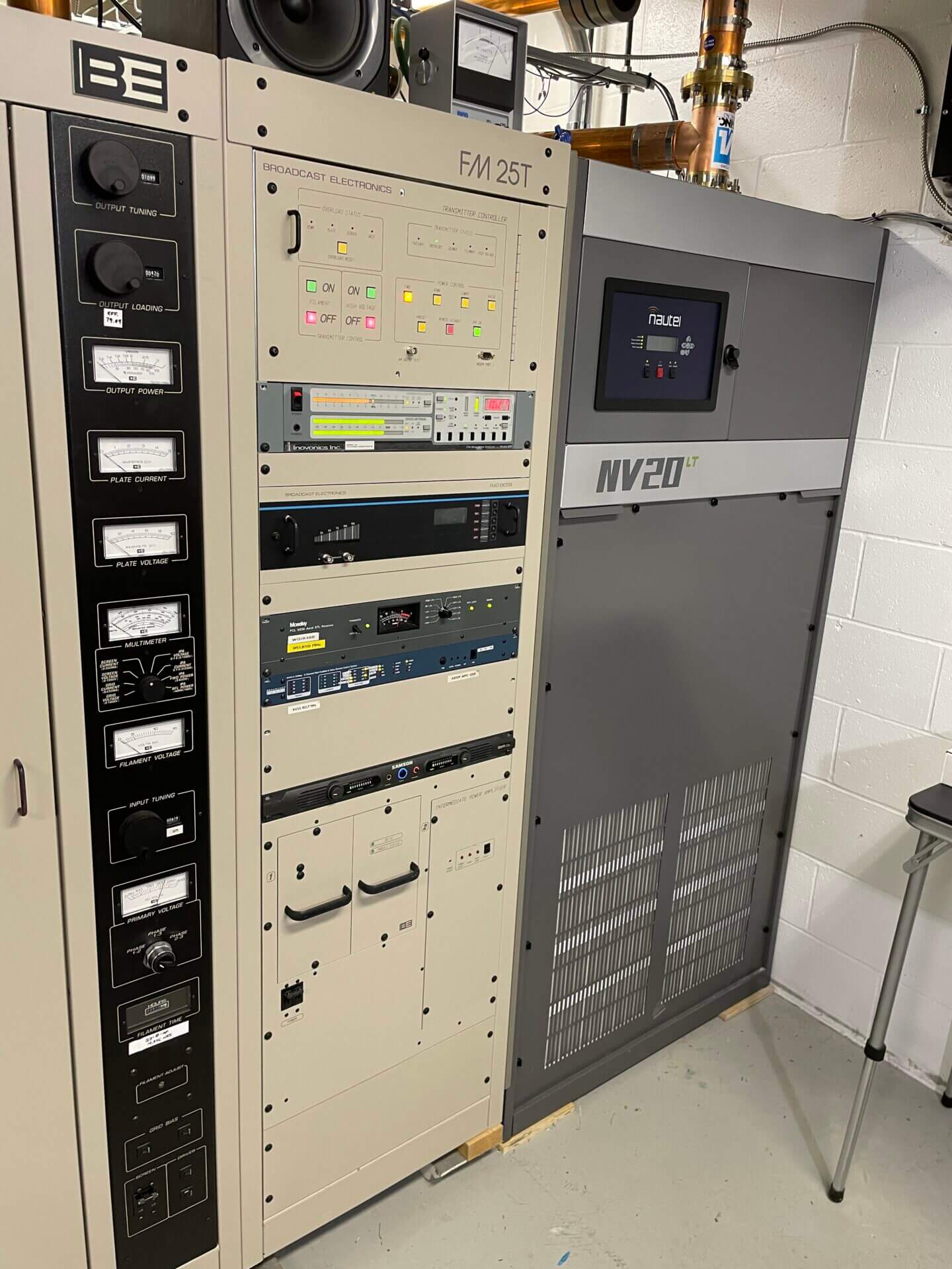
KVSS 102.7
Location: Southwest of Omaha, NE
Effective radiated power ERP: 46.1 kW
Antenna height above ground AGL: 1,270 feet
Main Transmitter: Nautel NV20LT solid state type
Backup Transmitter: BE FM25T tube type
KOLB 88.3
Location: Northwest of Osmond, NE
Effective radiated power ERP: 100 kW
Antenna height above ground AGL: 370 feet
Transmitter: BE FM25T tube type
Within the next year the BE will be replaced with a new Nautel 30 kW transmitter, keep checking back for progress reports!
KJWM 91.5
Location: South of Wood River, NE
Effective radiated power ERP: 35 kW
Antenna height above ground AGL: 591 feet
Main Transmitter: Nautel NV15LT solid state type
Backup Transmitter: BE FM5C solid state type
KEJS 88.1
Location: North of Weissert, NE
Effective radiated power ERP: 1.2 kW
Antenna height above ground AGL: 249 feet
Main Transmitter: Nautel VX1 Solid state type
KFJS 90.1
Location: North of North Platte, NE
Effective radiated power ERP: 13.2 kW
Antenna height above ground AGL: 335 feet
Main Transmitter: Elenos ETG10000 solid state type
Backup Transmitter: Elenos ETG2000 solid state type
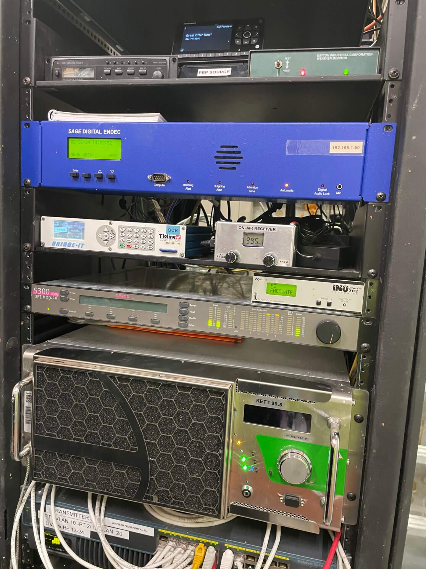
KETT 99.5
Location: South of Mitchell, NE
Effective radiated power ERP: 13 kW
Antenna height above ground AGL: 300 feet
Transmitter: Elenos ETG5000 solid state type
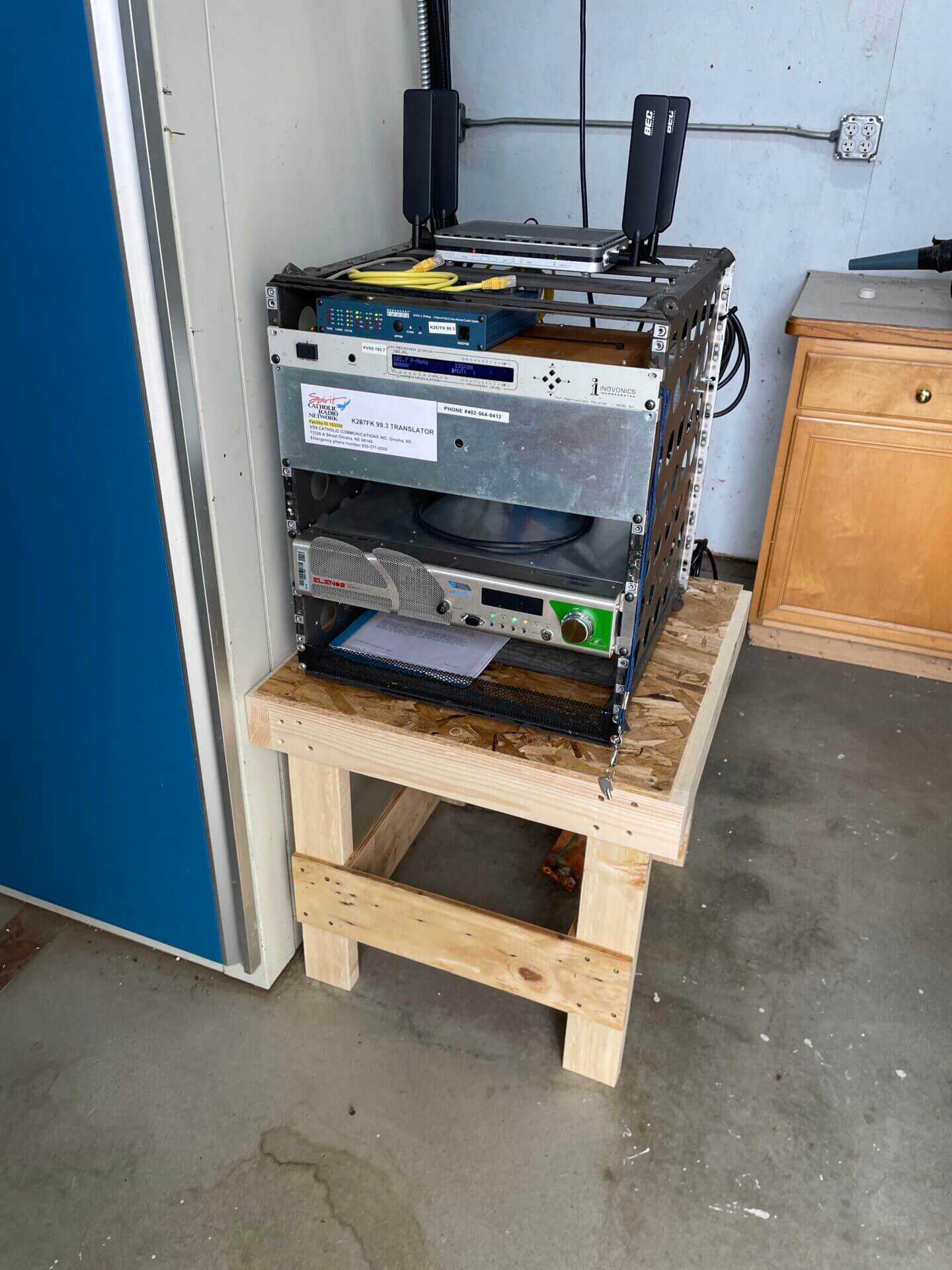
K257FK 99.3
Location: Northwest of Columbus, NE
Effective radiated power ERP: 250 W
Antenna height above ground AGL: 236 feet
Transmitter: Elenos ETG500 solid state type
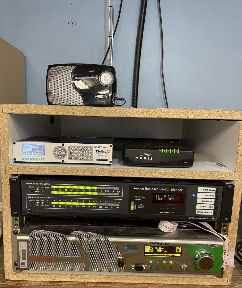
K217GM 91.3
Location: Chadron, NE
Effective radiated power ERP: 250 W
Antenna height above ground AGL: 85 feet
Transmitter: Elenos ETG500 solid state type
Our LPFM Affiliate Stations
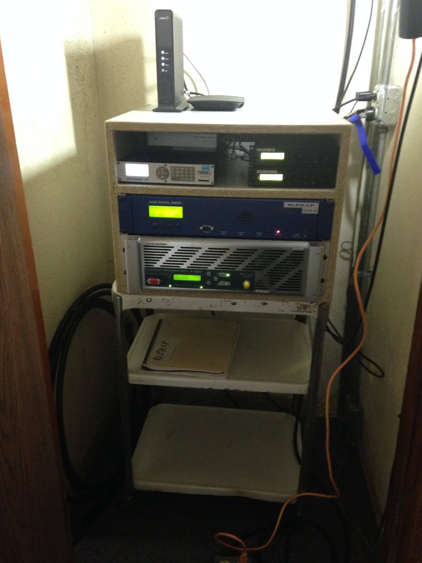
KLPH-LP 103.9
Location: Alliance, NE
Effective radiated power ERP: 100 W
Antenna height above ground AGL: 49 feet
Transmitter: Crown Ecreso FM350W solid state type
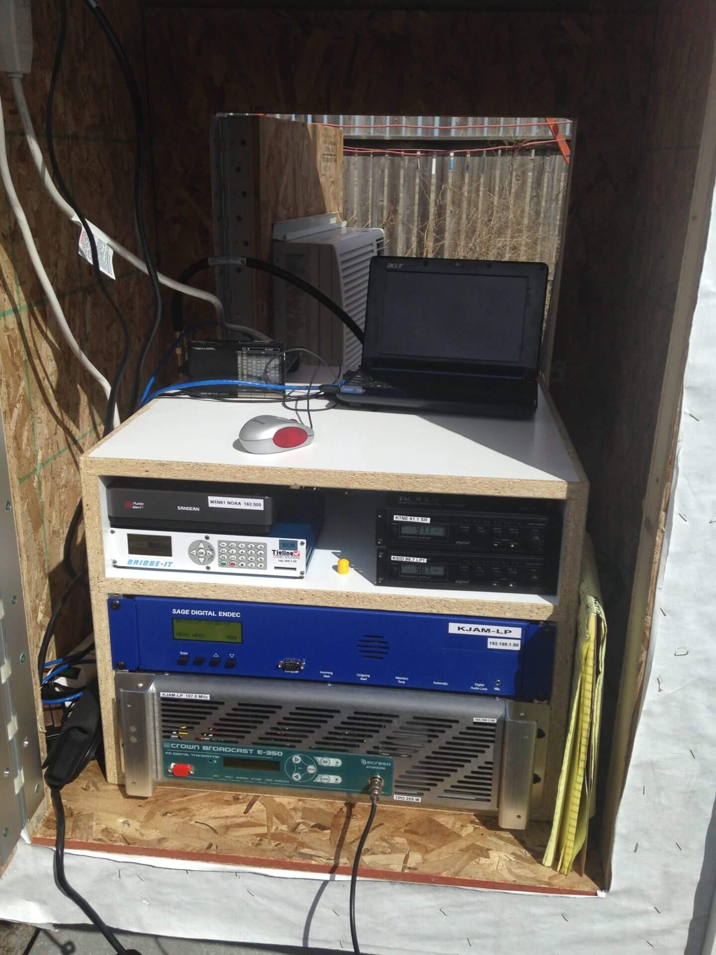
KJTJ-LP 107.5
Location: Sidney, NE
Effective radiated power ERP: 100 W
Antenna height above ground AGL: 101 feet
Transmitter: Crown Ecreso FM350W solid state type
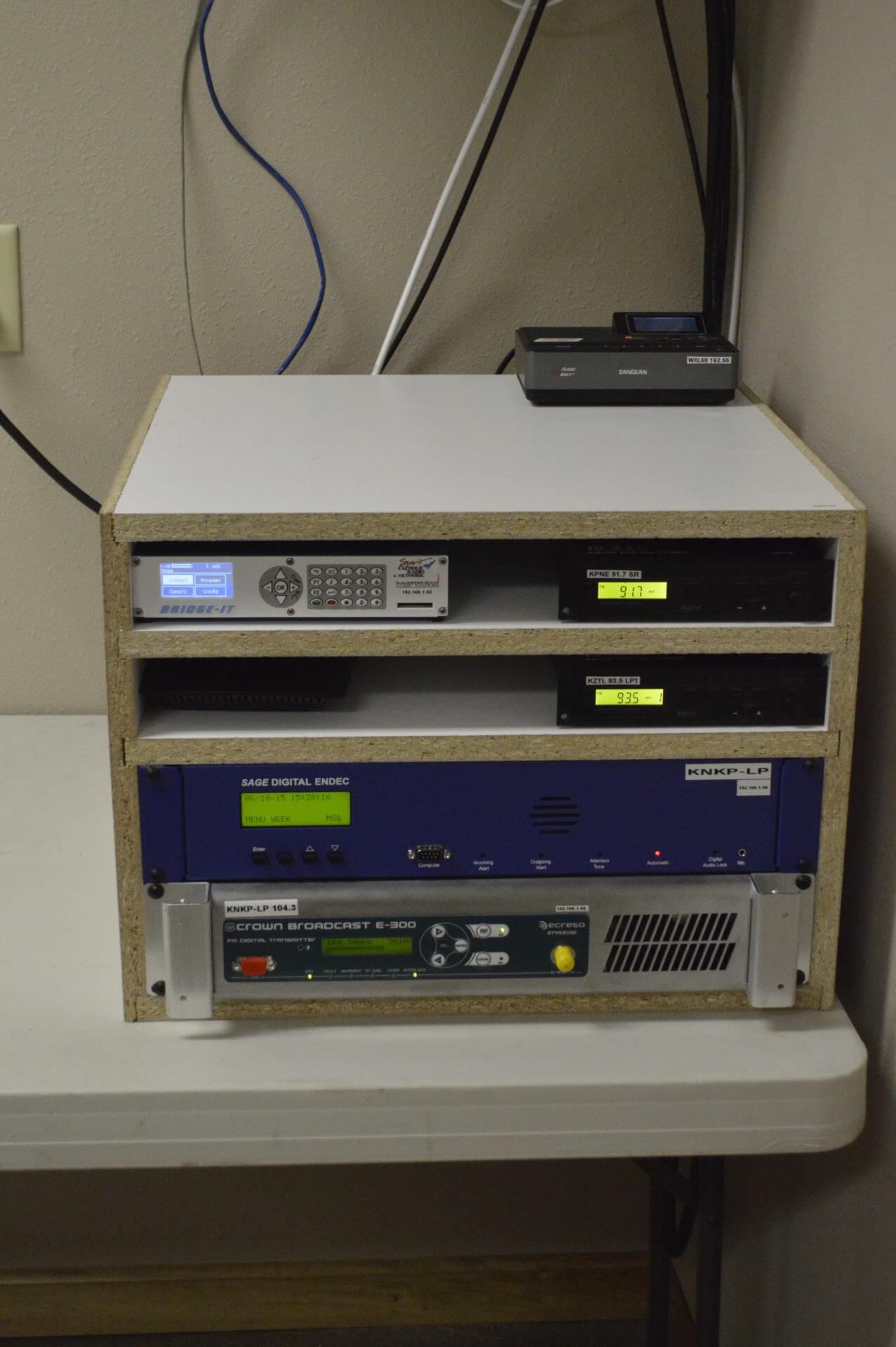
KNKP-LP 104.3
Location: Imperial, NE
Effective radiated power ERP: 100 W
Antenna height above ground AGL: 75 feet
Transmitter: Crown Ecreso FM300W solid state type
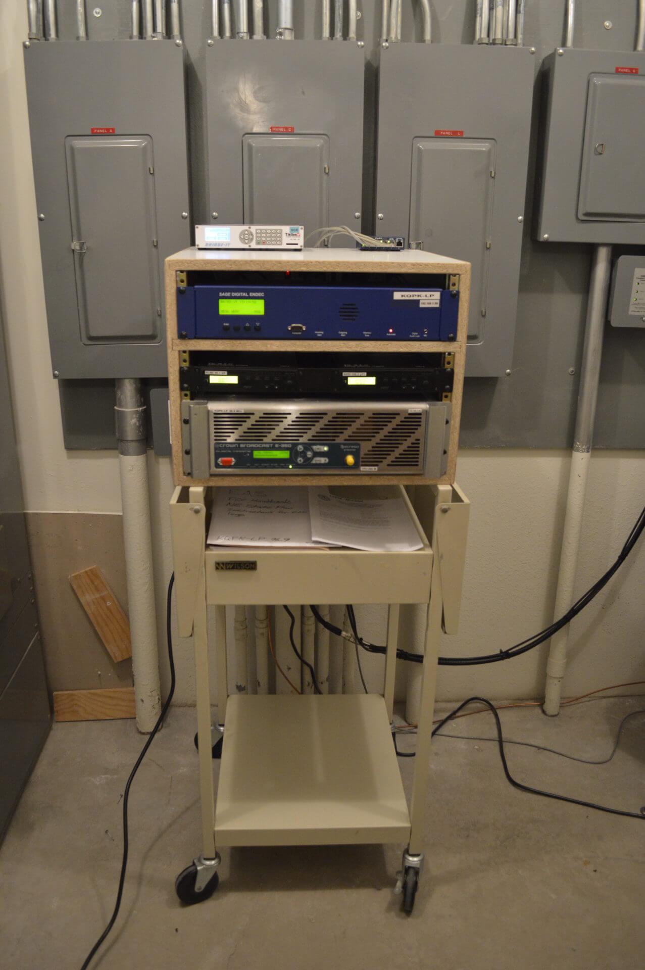
KQPK-LP 96.9
Location: McCook, NE
Effective radiated power ERP: 100 W
Antenna height above ground AGL: 52 feet
Transmitter: Crown Ecreso FM350W solid state type

KMKP-LP 106.5
Location: Holdrege, NE
Effective radiated power ERP: 100 W
Antenna height above ground AGL: 49 feet
Transmitter: Crown Ecreso FM300W solid state type

KPKA-LP 100.1
Location: Beatrice, NE
Effective radiated power ERP: 100 W
Antenna height above ground AGL: 78 feet
Transmitter: Crown Ecreso FM300W solid state type
KMAY-LP 102.5
Location: York, NE
Effective radiated power ERP: 100 W
Antenna height above ground AGL: 39 feet
Transmitter: Crown Ecreso FM300W solid state type
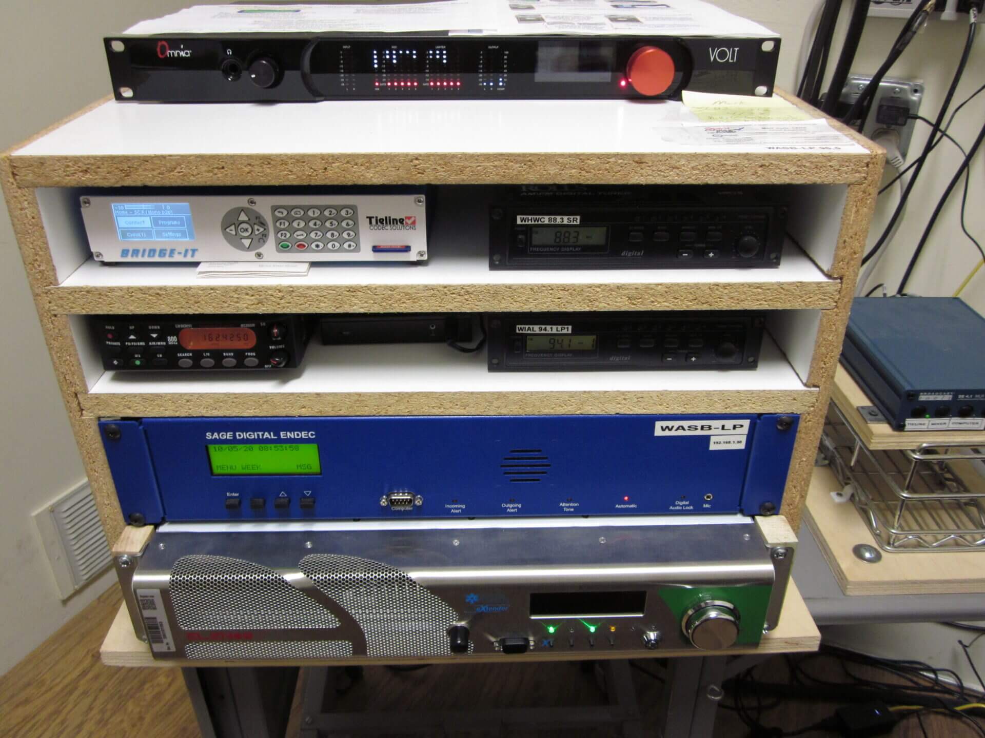
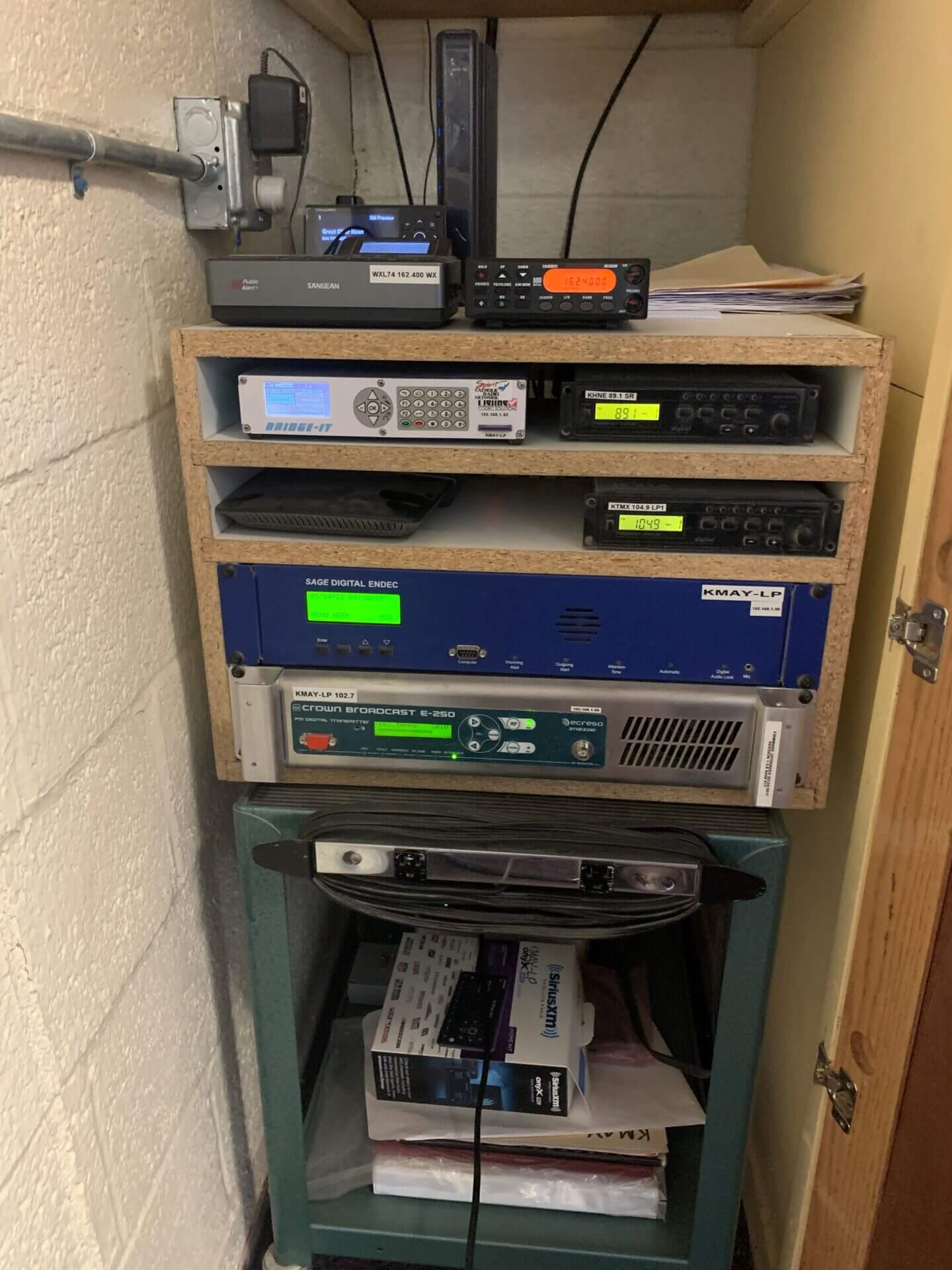
WASB-LP 96.5
Location: Boyd, WI
Effective radiated power ERP: 100 W
Antenna height above ground AGL: 59 feet
Transmitter: Elenos ETG500 solid state type
WASB-LP also has a co-located studio and air their weekend Masses.